Technical Blog Post
Abstract
Clustering with Maximo and WebSphere 8.5.5 - Part 2 - JMS Configuration
Body
Previously I had posted a blog on creating a horizontal cluster across multiple nodes in WebSphere 8.5.5. If you haven't read that posting, please head on over Clustering with Maximo and WebSphere 8.5.5 - Part 1 - Configuration and take a look. Today we will be continuing forward with JMS configuration. I was going to do this series in 2 parts, but I will separate this out in 3 parts due to the length of the topic.
In the original blog posting we configured the following.
mxcluster1
- DMGR
- IHS
- Node 1 w/ MAXIMOUI1
mxcluster2
- Node 2 w/ MAXIMOUI2, MAXIMOIF
This is a basic configuration, for larger companies, more UI's could be added, as well as clusters for CRON and BROS functionality. In our example the MIF JVM will function as a CRON JVM as well.
Today we will be going over the JMS queue configuration.
JMS\Queue configuration
Before we get into the Maximo stuff, we will want to configure the queues to run on the correct JVMs. We want all incoming transactions to be processed by the MIF JVM and all outbound transaction to be processed by the MAXIMOUI.
- SQOUT - MAXIMOUI
- SQIN - MAXIMOIF
- CQIN - MAXIMOIF
- CQINERR - MAXIMOIF
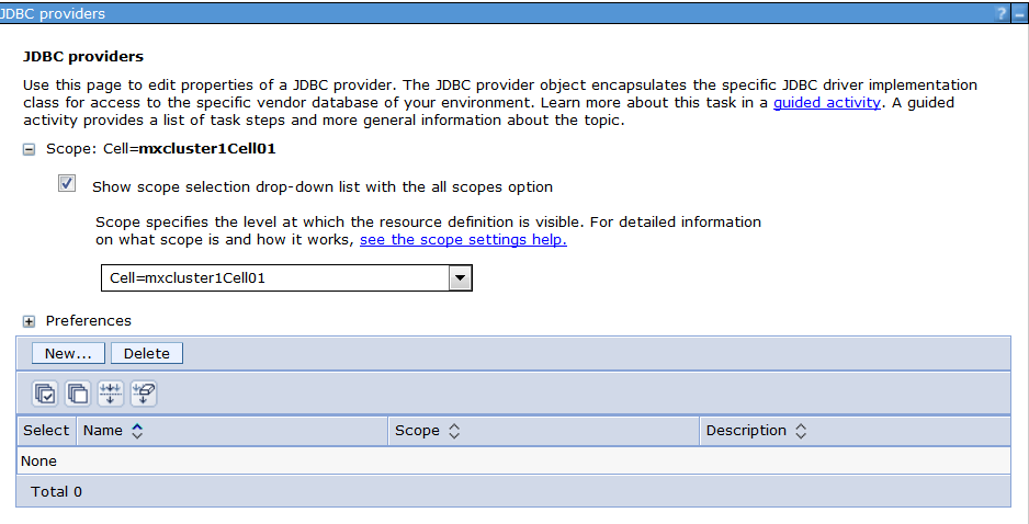
1. To start off we will create our JDBC Provider, expand 'Resources' - > 'JDBC' and click on 'JDBC Provider'. Set the scope to your cell level as seen below then click on 'New'
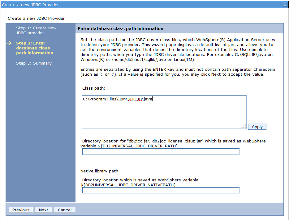
2. On the next screen you will be prompted for your JDBC provider Configuration info. We are using DB2 for our Database, but you will want to choose the Database Driver and Type associated with the Database you are running Maximo on.

3. Next we want to point to the database driver for DB2, this is db2jcc.jar, for Oracle it would be oraclethin and SQL Server opta. In the example below I pointed the class path directly to the DB2 folder with the DB2 driver. This driver will be required to exist on each of the nodes in the cluster. Click Apply, Next and Finish.
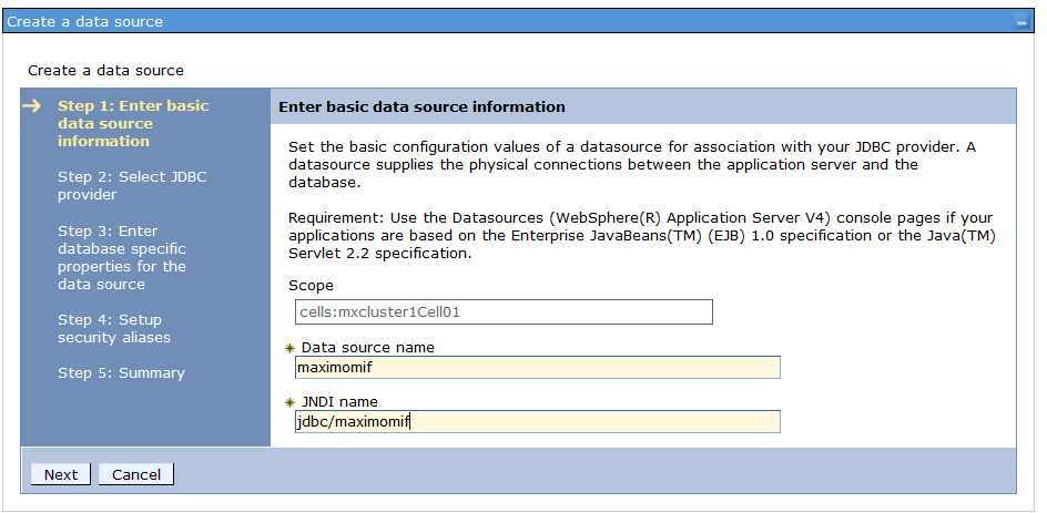
4. Now that we have the driver configured that we will be using to connect to our database, we want to create two data sources, one for the UI and one for the MIF. Each of these data sources need to point to different unique schema's. We left our UI data source pointing to the Maximo schema and created a separate schema for the MIF data source. Our MIF data source will be called 'maximomif' with a JNDI name of 'jdbc/maximomif'. Click next.
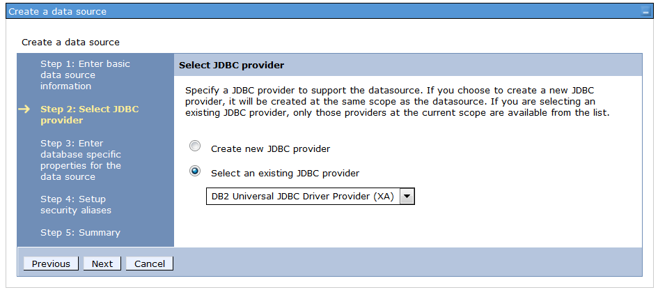
5. On the next screen select the JDBC driver created in step two and click next
7. On the next step of creating the data source we will need to point to our database for 'maximomif' we created our new schema under the Maximo database, so this is where we are going to point the data source. We will point to the specific schema in the bus configuration.
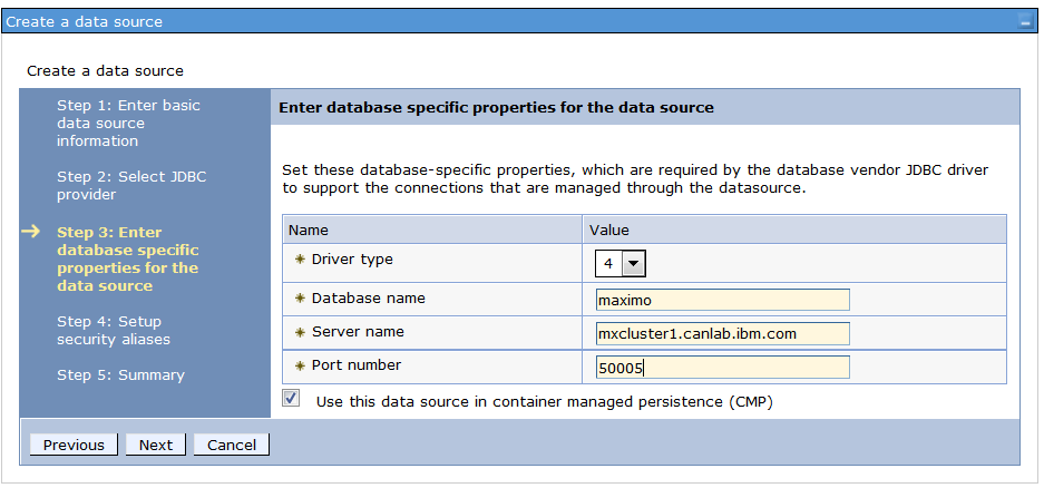
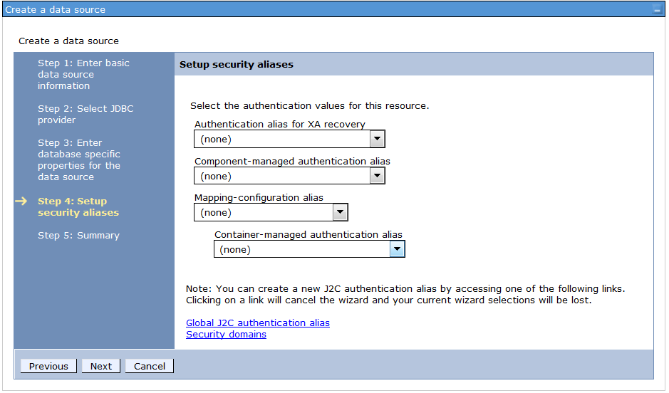
8. We will skip the security configuration for now and setup our component-managed authentication alias in the next step. Click next and finish.
9. Once your 'maximomif' data source is created, click on it from the main data source page in WebSphere. Under related items click on 'JAAS- J2C authentication data.'
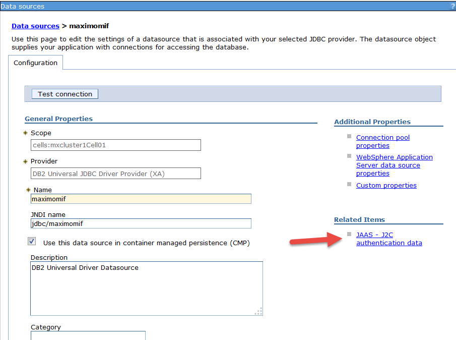
10. Click on new, give this an authentication alias of maximomif and enter in the userid and password that will be used to connect to the schema from your data source.Click Apply.

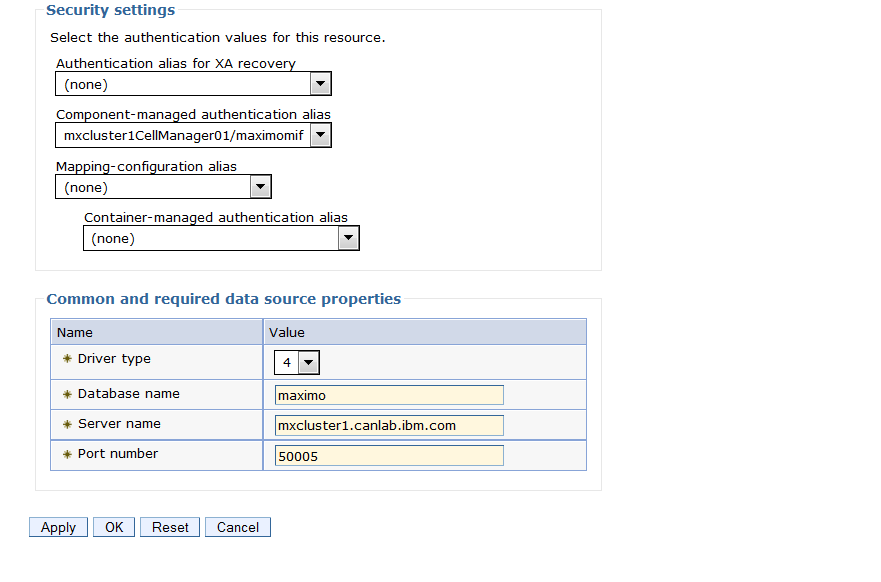
11. Head back to the 'maximomif' data source configuration page, at the bottom select your 'maximomif' alias in the 'Component-Managed authentication alias' drop down. Click Apply and save to the master configuration.
12. Repeat steps 4 to 11 for a data source with a name of 'maximoui' and JNDI name of jdbc/maximoui. Create the authentication alias called maximoui for a user that has access to the schema the UI data source will be connecting to ( in our case UI will be connecting to the maximo schema)
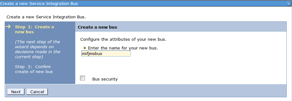
13. Now that our Data Sources are created we will want to create our buses. 'mifjmsbus' will run on the MAXIMOIF jvm and 'uijmsbus' will run on the UI Cluster. From the WebSphere Console expand 'Service Integration' - > 'Buses' and click on New. Enter in the first bus name 'mifjmsbus' and uncheck 'Bus Security'. Click Next and Finish. Repeat this step to create a bus for your user cluster called 'uijmsbus'
14. Once both of your buses are created click on the 'mifjmsbus' then click 'Bus members' then click 'Add'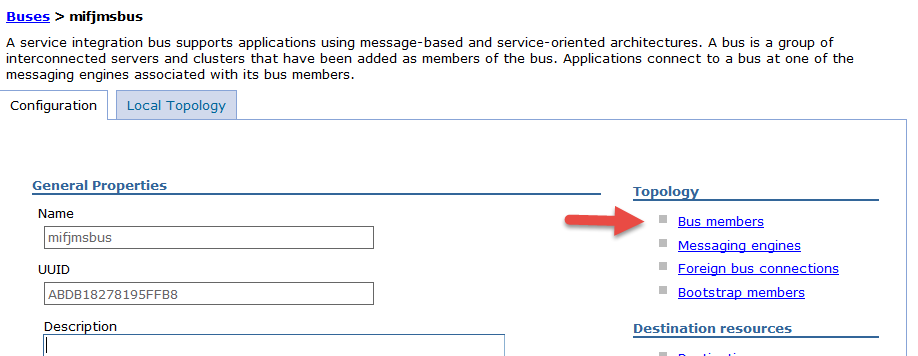
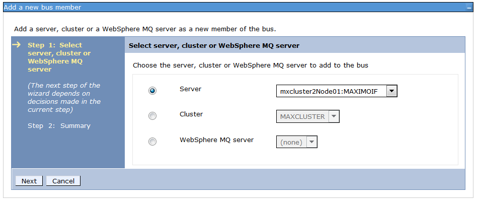
15. the 'mifjmsbus' will be be assigned the MAXIMOIF JVM as it's member. Click Next and choose Data Store for your type of message store.
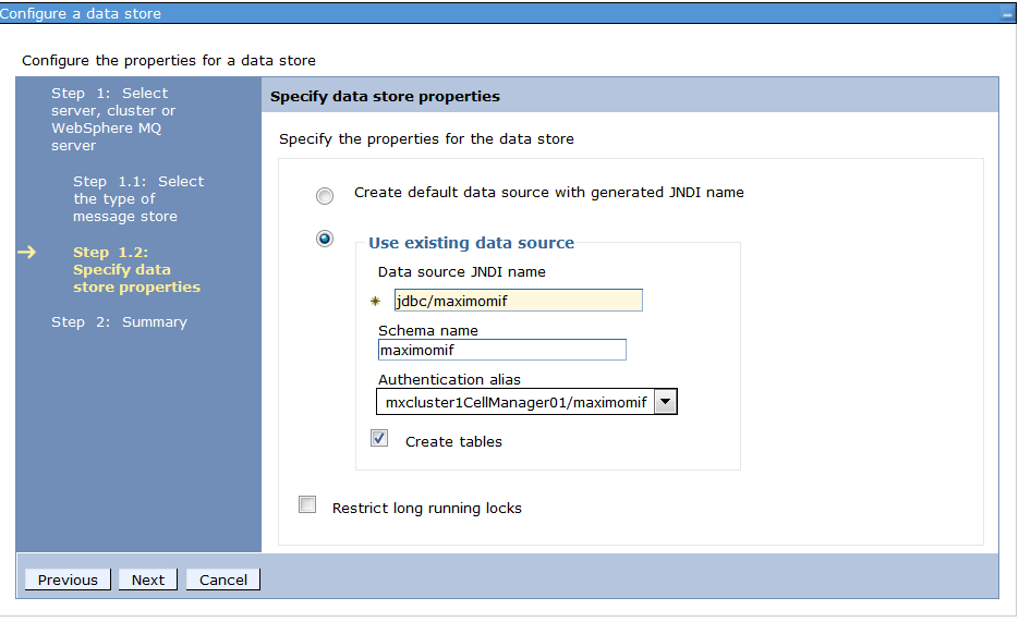
16. Enter your data source JNDI name for the MIF data source 'jdbc/maximomif'. Here is where we will be specifying the schema we created unique to the maximomif data source, ours is called 'maximomif' as well. Then select the the authentication alias created earlier and check the 'Create Tables' box. Click next and finish.
17. As you did in step 14 for the 'mifjmsbus', click on the 'uijmsbus' and then click on 'Bus members' then click 'Add'. Instead of choosing an individual server, we will choose the MAXCLUSTER we created for the UI.
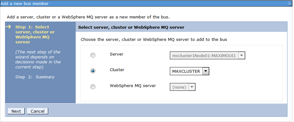
18. Again choose data store as your message store and enter in the JNDI name, schema name and authentication alias for for your UI data source. Check create tables and click Next and Finish. 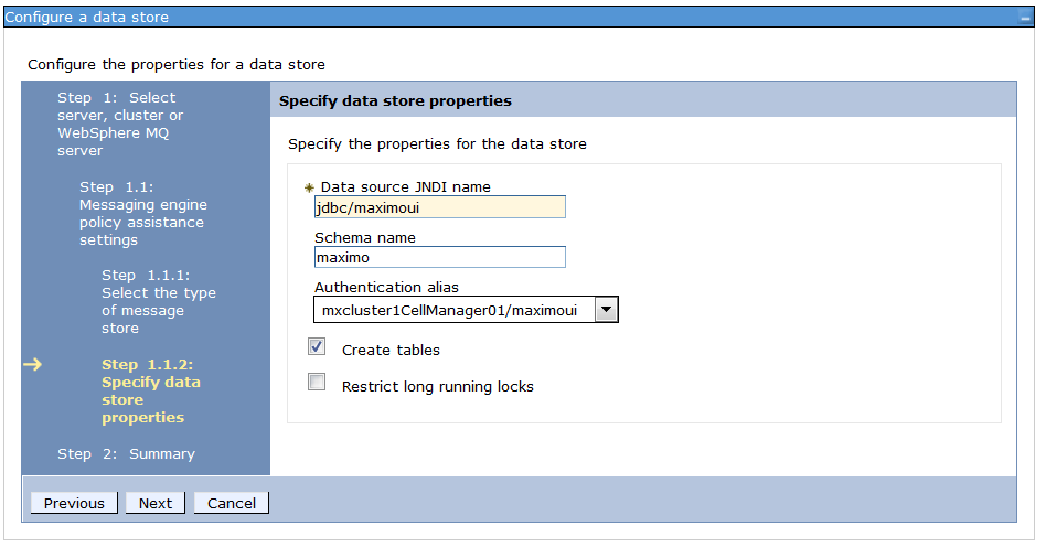
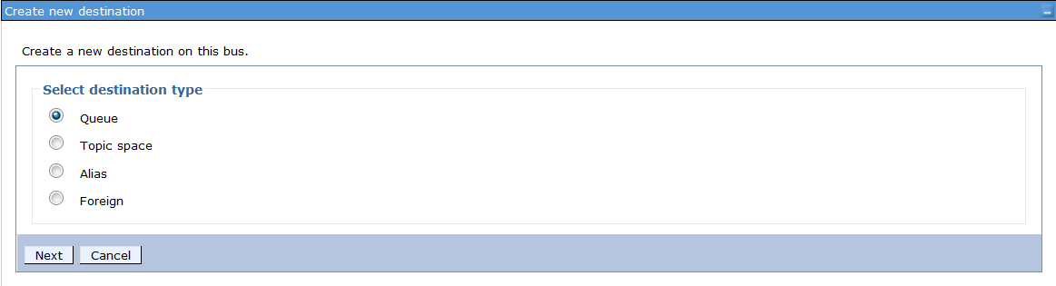
19. Now we have our Data Sources and Buses configured for both the UI Cluster and MIF JVM's. We now need to create the destinations on each of the buses. Click on the 'mifjmsbus' once more under 'Destination Resources' choose 'Destinations' Click on new, choose 'Queue' then click Next.
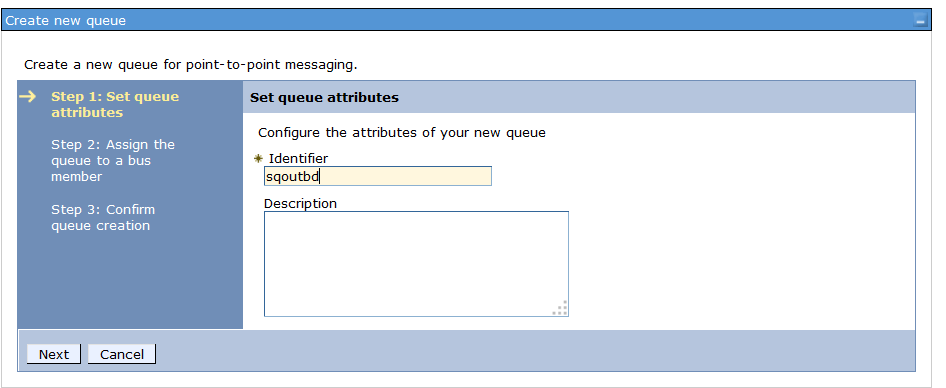
20. Your first queue will be called 'cqindb' click Next
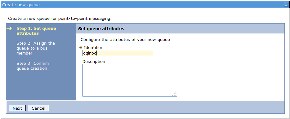
21. Assign this Queue to the MAXIMOIF bus member. Click Next and Finish. Now Repeat steps 19 - 21 for 'sqinbd' and 'cqindberr'.
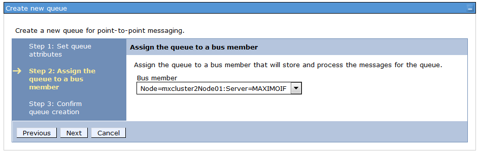
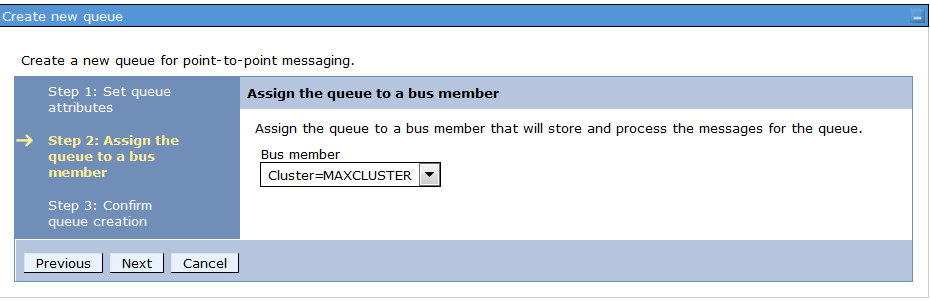
22. Now click on the 'uijmsbus' once more under 'Destination Resources' choose 'Destinations' click on new, choose 'Queue' then click Next. We now want to create 'sqoutbd'
23. Assign this to the MAXCLUSTER bus member, click Next and Finish.
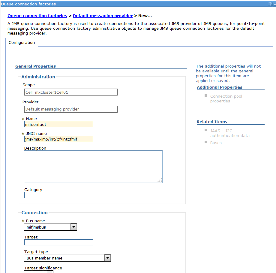
24.The queues are now created and assigned to the appropriate bus members. The next step is creating our connections factories. From the WebSphere console expand 'Resources' - > 'JMS' and click on 'Queue Connection Factories'. Change the scope to the cell level and click on new, choose 'Default messaging provider' and click OK. Give the connection factory the following properties and save the record.
Name: mifconfact
JNDI name: jms/maximo/int/cf/intcfmif
Bus Name: mifjmsbus
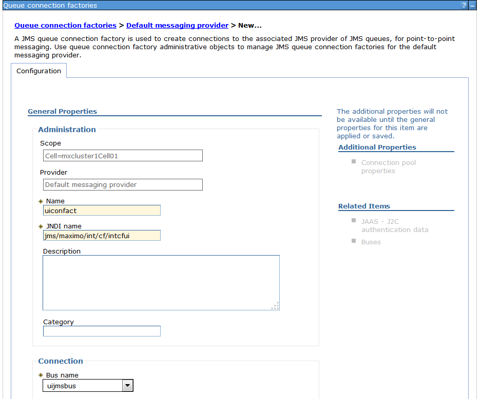
25. Now we need to repeat the last step for the UI connection factory with the following properties
Name: uiconfact
JNDI name: jms/maximo/int/cf/intcfui
Bus Name: uijmsbus
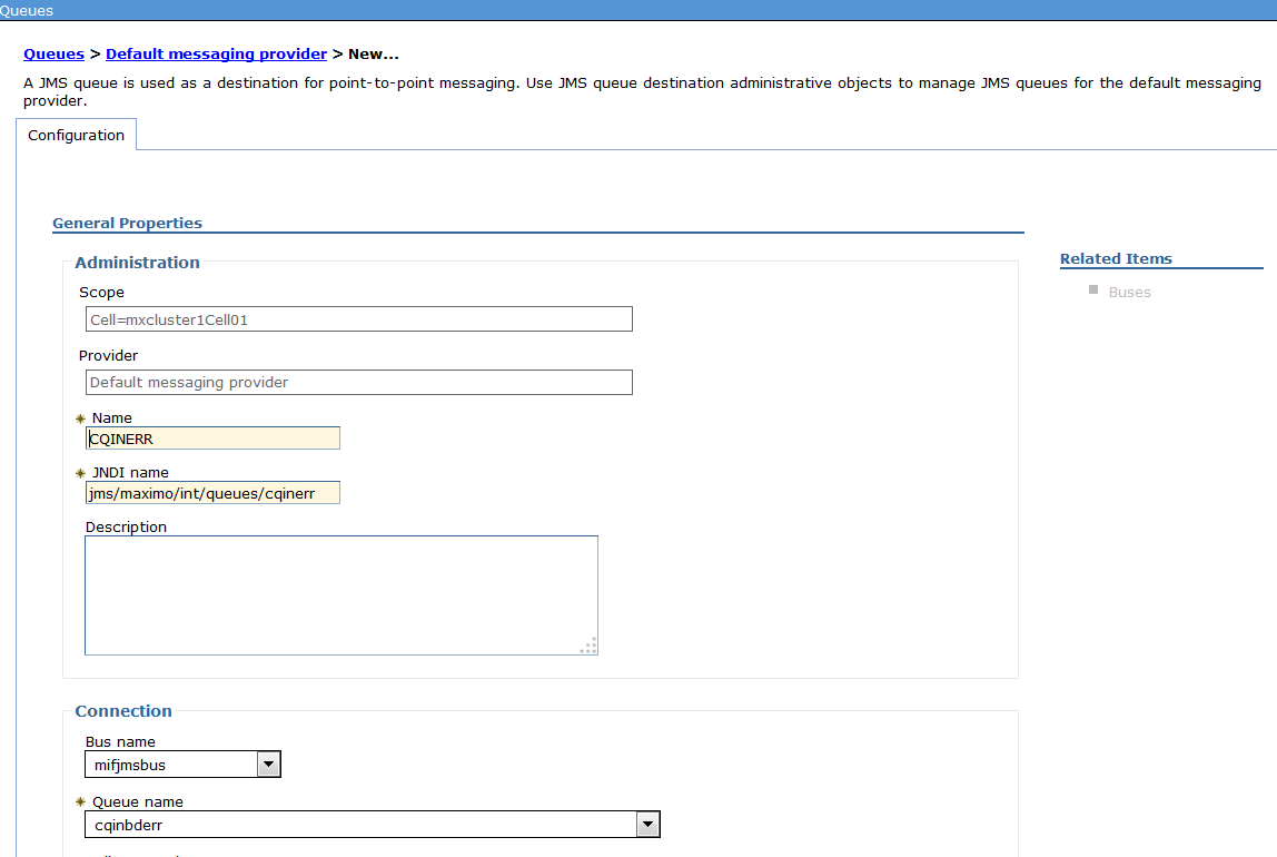
26. Now expand 'Resources' - > 'JMS' and click 'Queues'. Set the scope to the cell level and click new. The first queue we will create here is the CQINERR with the following properties.
Name: CQINERR
JNDI name: jms/maximo/int/queue/cqinerr
Bus name: mifjmsbus
Queue name: cqinbderr
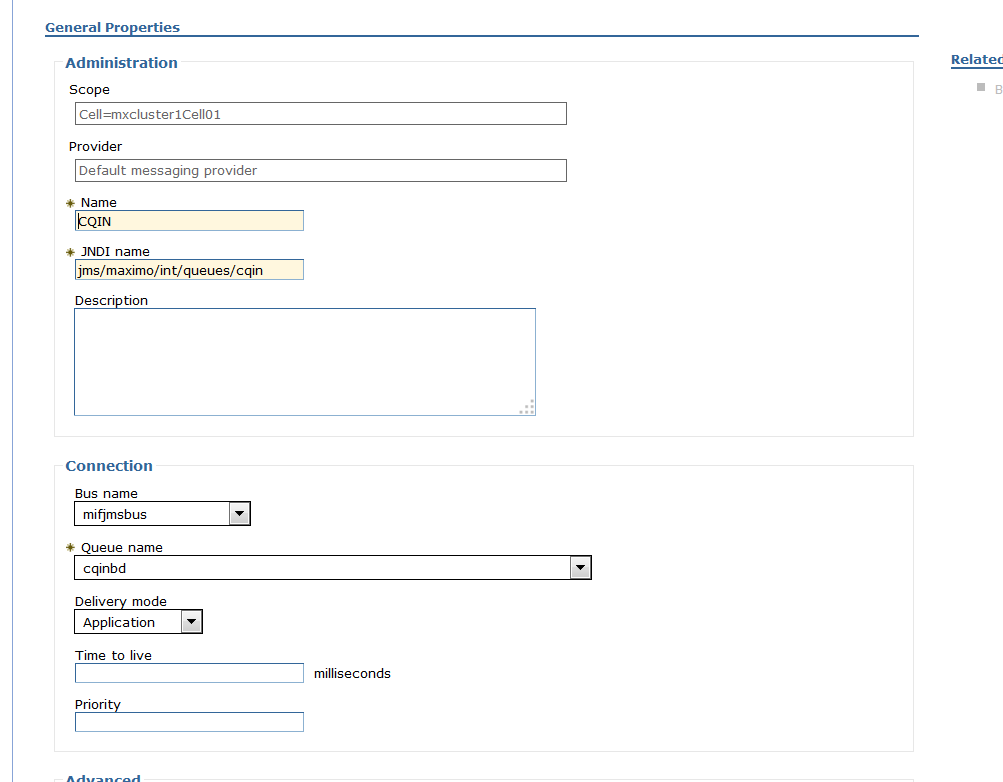
27. Repeat step 26 for CQIN with the following properties
Name: CQIN
JNDI name: jms/maximo/int/queue/cqin
Bus name: mifjmsbus
Queue name: cqinbd
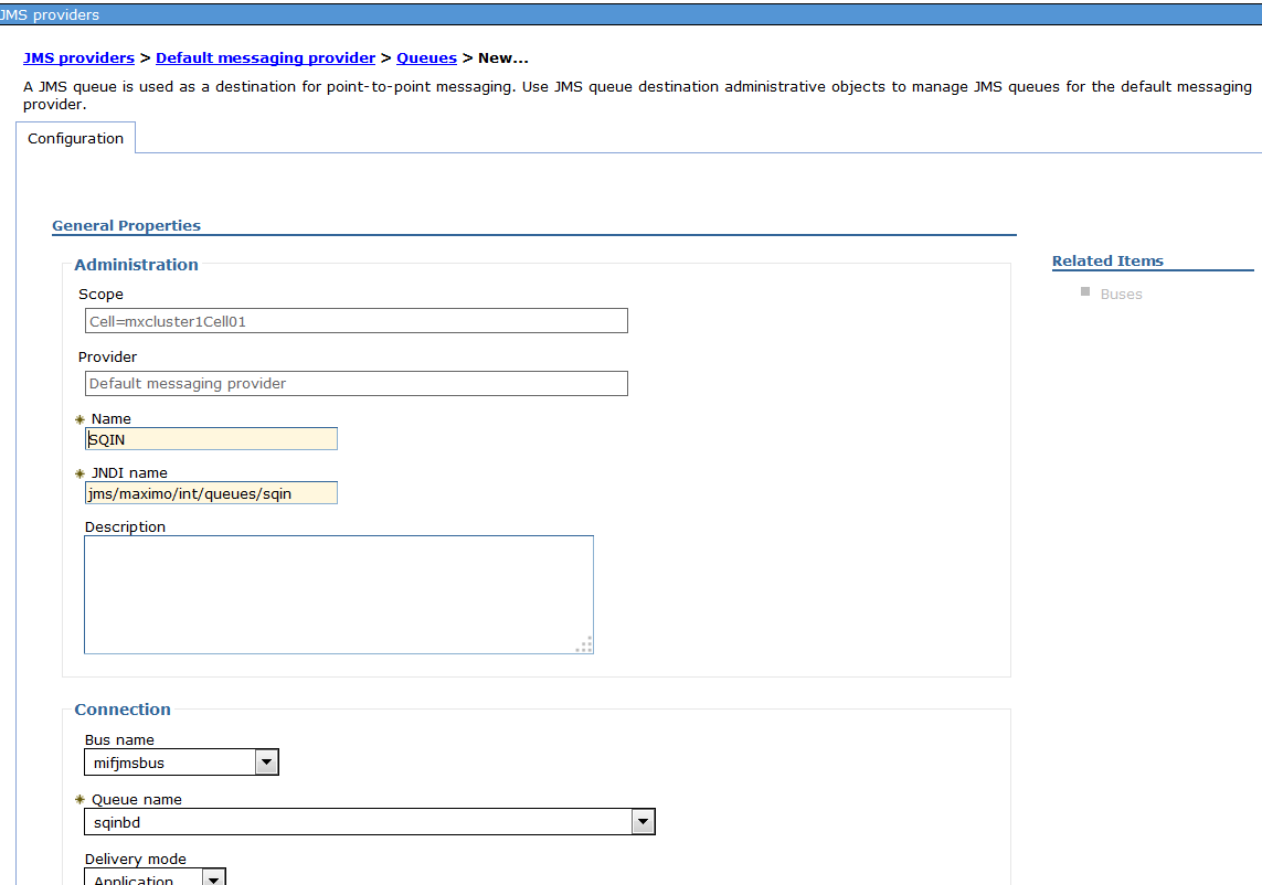
28. Repeat step 26 for SQIN with the following properties
Name: SQIN
JNDI name: jms/maximo/int/queue/sqin
Bus name: mifjmsbus
Queue name: sqinbd
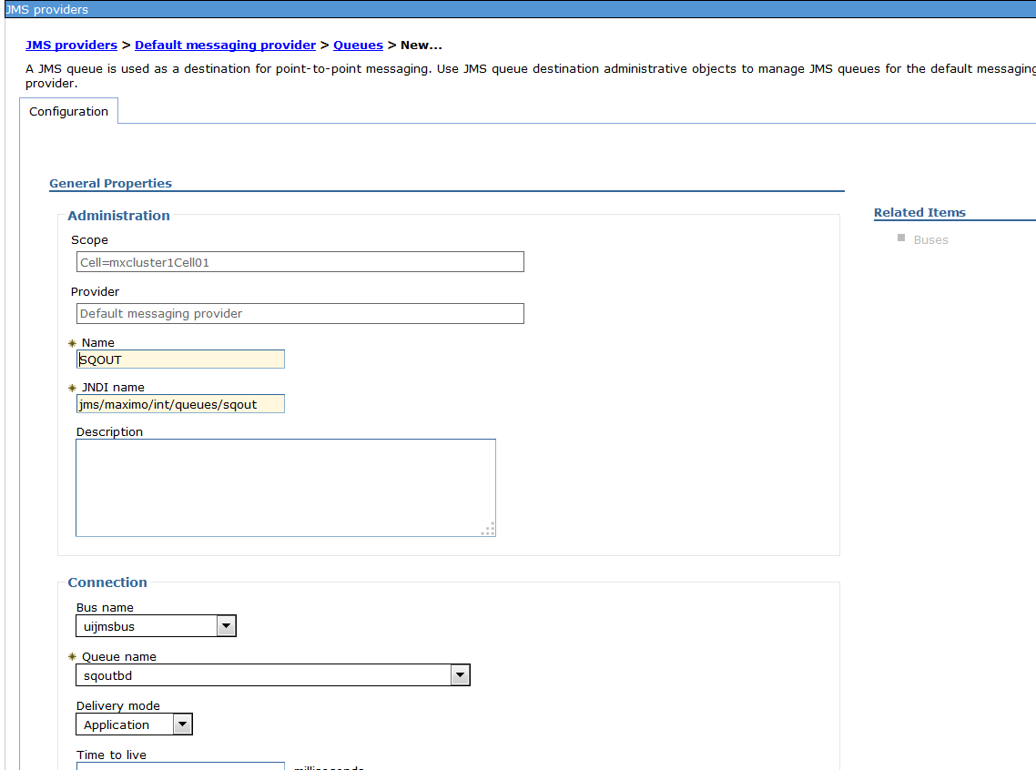
29. Repeat step 26 for SQOUT for the 'uijmsbus'
Repeat step 26 for SQIN
Name: SQOUT
JNDI name: jms/maximo/int/queue/sqout
Bus name: uijms
Queue name: sqoutbd
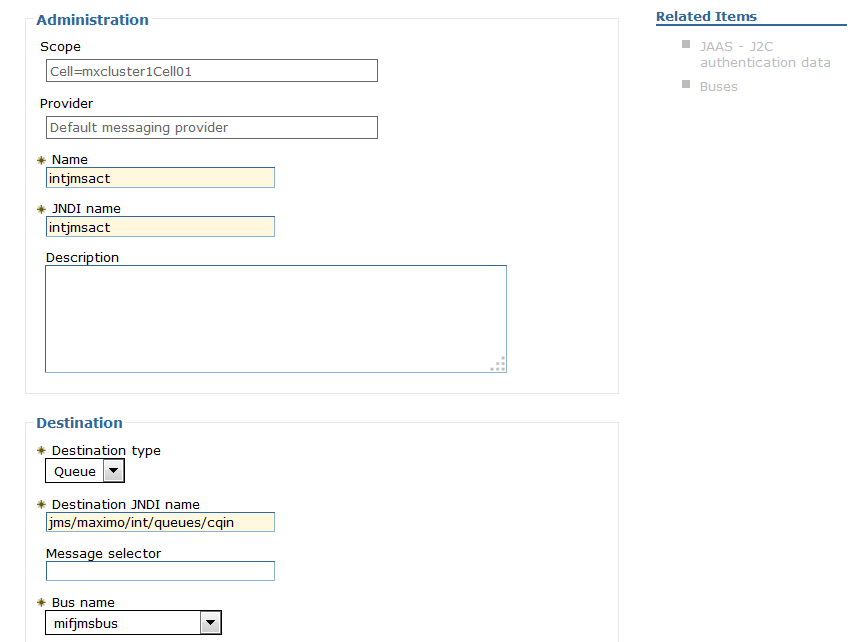
30. Our last steps for the WebSphere JMS configuration is the Activation Specification for the CQIN and CQINERR. From the WebSphere Console expand 'Resource' - > 'JMS' and click on 'Activation specifications'. Set the scope to the cell level click on 'new' and choose 'Default messaging provider'. Create the first Activation Specification with the following properties.
Name: intjmsact
JNDI name: intjmsact
Destination Type: Queue
Destination JNDI name: jms/maximo/int/queues/cqin
Bus name: mifjmsbus
Now repeat the above steps for another Activation spec with the following properties.
Name: intjmsacterr
JNDI name: intjmsacterr
Destination Type: Queue
Destination JNDI name: jms/maximo/int/queues/cqinerr
Bus name: mifjmsbus
That should do it for today's post, at this point your cluster is configured with 2 UI JVM's and a separate MIF\Cron JVM. The JMS configuration is setup to run the sqout on the UI and the cqin,cqinerr and cqin on the MIF JVM. Part 3 will finish off the series with the Maximo file configuration,Virtual Host\Deployment of the ear files and separating the cron task\escalations to the MIF JVM.
Series
Clustering with Maximo and WebSphere 8.5.5 - Part 1 - Configuration
Clustering with Maximo and WebSphere 8.5.5 - Part 2 - JMS Configuration
Clustering with Maximo and WebSphere 8.5.5 - Part 3 - Isolating Functionality and Deployment
UID
ibm11113741