Product Documentation
Abstract
This document contains a table entitled System board diagrams - IBM Netfinity 7600
Content
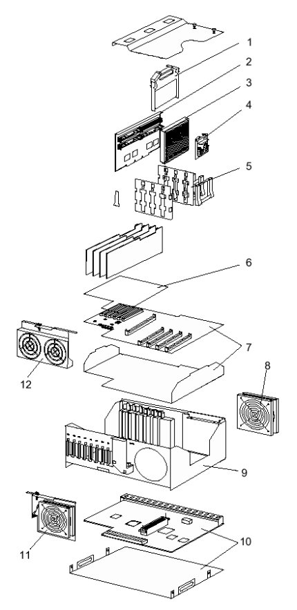
The IBM Netfinity 7600 is comprised of several system boards:
- Input/Output (I/O) board component locations
- Processor board LEDs
- Processor board connectors
- Processor board jumpers
- Memory board LEDs
- Memory board connectors
NOTE: The illustrations in this document might differ slightly from your hardware.
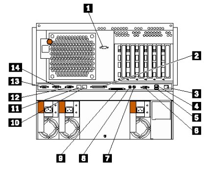
I/O board component locations
The following illustration identifies the connectors on the I/O board.
| Index | Description |
|---|---|
| 1 | Power backplane connector |
| 2 | Processor board connector |
| 3 | Ethernet port connector (J14) |
| 4 | USB 1 and USB 2 port connectors (J31) |
| 5 | Video port connector (J2) |
| 6 | Mouse connector (J30) |
| 7 | Keyboard connector (J32) |
| 8 | SCSI external connector (J21) |
| 9 | Parallel port connector (J33) |
| 10 | ASM Interconnect connector (J10) |
| 11 | Serial port B connector (J15) |
| 12 | Serial port A connector (J16) |
| 13 | Management port connector (J18) |
back to top
Processor board LEDs
The following illustration identifies the location of the LEDs.
| Index | Description |
|---|---|
| 1 | Microprocessor 1 error LED (CR9) |
| 2 | Microprocessor 2 error LED (CR3) |
| 3 | Microprocessor 3 error LED (CR8) |
| 4 | Microprocessor 4 error LED (CR4) |
| 5 | Battery |
| 6 | PCI |
| 7 | VRM 4 error LED (CR10) |
| 8 | VRM 3 error LED (CR5) |
| 9 | VRM 2 error LED (CR7) |
| 10 | VRM 1 error LED (CR6) |
Processor board connectors
The following illustration identifies the location of the connectors.
| Index | Description |
|---|---|
| 1 | Microprocessor 1 connector |
| 2 | Microprocessor 2 connector |
| 3 | Microprocessor 3 connector |
| 4 | Microprocessor 4 connector |
| 5 | Memory board connector |
| 6 | Battery |
| 7 | PCI slots 3-6 (on PCI bus B) |
| 8 | PCI slots 1-2 (on PCI bus A) |
| 9 | VRM 4 connector |
| 10 | VRM 3 connector |
| 11 | VRM 2 connector |
| 12 | VRM 1 connector |
Processor board jumpers
The following illustration identifies the location of the jumpers.
| Index | Description |
|---|---|
| 1 | Jumper block (J8) (Reserved) |
| 2 | Jumper block (J9) (Reserved) |
| 3 | Jumper block (J10-J16) |
| 4 | Flash ROM page-swap jumper block (J56) |
| 5 | Power-on passwordoverride jumper block (J48) |
| 6 | Battery |
| 7 | Power-on control jumper block (J23) |
| 8 | 3.3 V standby power for slot 2 (J20) |
| 9 | 3.3 V standby power for slot 1 (J47) |
| 10 | Advanced System Management Processor reset jumper block (J59) |

| Index | Description |
|---|---|
| 1 | Microprocessor core-frequency-selection jumper block (J13-J16) |
| 2 | Reserved (J10) |
| 3 | Reserved (J12) |
| 4 | Reserved (J11) |
Memory board LEDs
The following illustration identifies the location of the LEDs on the memory board.
| Index | Description |
|---|---|
| 1 | Connector 1 (J1) |
| 2 | Connector 2 (J2) |
| 3 | Connector 3 (J3) |
| 4 | Connector 4 (J4) |
| 5 | Connector 5 (J5) |
| 6 | Connector 6 (J6) |
| 7 | Connector 7 (J7) |
| 8 | Connector 8 (J8) |
| 9 | Connector 9 (J9) |
| 10 | Connector 10 (J10) |
| 11 | Connector 11 (J11) |
| 12 | Connector 12 (J12) |
| 13 | Connector 13 (J13) |
| 14 | Connector 14 (J14) |
| 15 | Connector 15 (J15) |
| 16 | Connector 16 (J16) |
Memory board connectors
The following illustration identifies the location of the DIMM connectors on the memory board.
| Index | Description |
|---|---|
| 1 | DIMM 1 error LED (CR4) |
| 2 | DIMM 2 error LED (CR5) |
| 3 | DIMM 3 error LED (CR2) |
| 4 | DIMM 4 error LED (CR1) |
| 5 | DIMM 9 error LED (CR13) |
| 6 | DIMM 10 error LED (CR12) |
| 7 | DIMM 11 error LED (CR15) |
| 8 | DIMM 12 error LED (CR16) |
| 9 | DIMM 13 error LED (CR11) |
| 10 | DIMM 14 error LED (CR14) |
| 11 | DIMM 15 error LED (CR10) |
| 12 | DIMM 16error LED (CR9) |
| 13 | Processor board connector |
| 14 | DIMM 8 error LED (CR8) |
| 15 | DIMM 7 error LED (CR7) |
| 16 | DIMM 6 error LED (CR3) |
| 17 | DIMM 5 error LED (CR6) |
Additional information
Document Location
Worldwide
Was this topic helpful?
Document Information
Modified date:
24 January 2019
UID
ibm1MIGR-52784