Product Documentation
Abstract
This document contains a table entitled IBM Netfinity 7000 M10 - System board diagrams
Content
The IBM Netfinity 7000 M10 is comprised of several different system boards and a SCSI backplane:
- SCSI backplane component locations
- Memory board component locations
- Processor board conponent locations
- Power backplane component locations
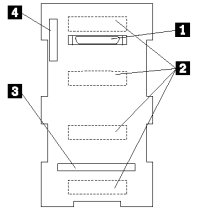
SCSI backplane component locations
The following illustration identifies the components of the SCSI backplane. Refer to this figure when you set the jumpers on the backplane.
Move the mouse over the index number in the illustration below. Click the index number to locate the description.
| Index | Description |
|---|---|
| 1 | Wide (16-bit) SCSI connector |
| 2 | SCSI hot-swap drive connectors (on opposite side of backplane) |
| 3 | SAF-TE SCSI card connector |
| 4 | Power connector |
Processor board component locations
The following illustration identifies the components of the system board.
Move the mouse over the index number in the illustration below. Click the index number to locate the description.
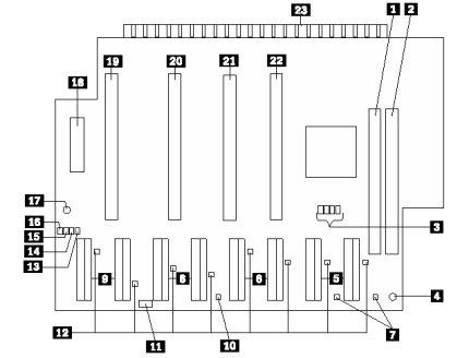
NOTES:
- Turn off the server, and disconnect the power cord before moving any jumpers.
- Be sure the microprocessor bus to core ratio is set correctly. For example, if you have a 450MHz microprocessor installed and the system bus speed is 100MHz (the default), be sure that the jumpers are set to a bus-to-core ratio of 4.5 (450/100).
- Be sure to set the Microprocessor Core Frequency Selection jumper block for the slowest speed microprocessor installed in your server. For example, if your server has a 400MHz microprocessor installed and you install three 450MHz microprocessors, set the Microprocessor Core Frequency Selection jumper block for the 400MHz microprocessor. MHz denotes internal clock speed of the microprocessor only; other factors also affect application performance.
WARNING: If the microprocessor bus to core ratio is incorrect, board components will overheat and component damage might occur. Be sure that the microprocessor bus to core ratio jumper is properly set.
Processor Board Jumpers| Index | Jumper Name | Description |
|---|---|---|
| 3 | Microprocessor core frequency selection (J43–J46) | The default core/bus fraction is 4.0 (400/100MHz). Jumpers are installed on pins 1 and 2 of J44, J45 and J46, and jumpers are installed on pins 2 and 3 of J43. For the core/bus fraction 4.5 (450/100 MHz), the jumpers are installed on pins 1 and 2 of J44, and J46, and jumpers are installed on pins 2 and 3 of J43 and J45. For the core/bus fraction 5.0 (500/100MHz), the jumpers are installed on pins 2 and 3 of J43, and J44, and jumpers are installed on pins 1 and 2 of J45 and J46. For the core/bus fraction 5.5 (550/100MHz), the jumpers are installed on pins 2 and 3 of J43, J44, and J45, and jumpers are installed on pins 1 and 2 of J46. |
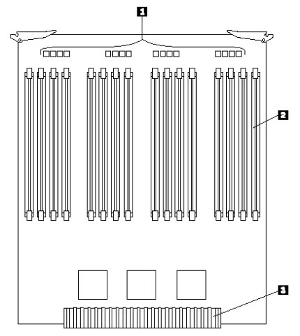
Memory board component locations
The following illustration identifies the components of the memory board.
Move the mouse over the index number in the illustration below. Click the index number to locate the description.
| Index | Description |
|---|---|
| 1 | DIMM error LEDs |
| 2 | DIMM connectors |
| 3 | Processor board connector |
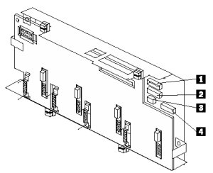
Power backplane component locations
The following illustration identifies the components of the power backplane.
Move the mouse over the index number in the illustration below. Click the index number to locate the description.
| Index | Description |
|---|---|
| 1 | Processor board connector |
| 2 | SCSI backplane connector |
| 3 | Fan connector (processor fans) |
| 4 | Fan connector (DASD fans) |
Additional information
Document Location
Worldwide
Was this topic helpful?
Document Information
Modified date:
24 January 2019
UID
ibm1MIGR-52710