Product Documentation
Abstract
This document contains a diagram of the system board of the Netfinity 4500R server.
Content
System board layout
The illustrations in the following sections show the components on the system board.
System board options connectors
The following illustration shows a layout of the system board and identifies system-board connectors for user-installable options.
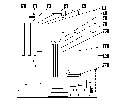
- PCI slot 5 32-bit (J44)
- Battery
- PCI slot 4 32-bit (J39)
- PCI slot 3 64-bit (J34)
- PCI slot 2 64-bit (J32)
- PCI slot 1 64-bit (J27)
- DIMM 1 (J23)
- DIMM 2 (J21)
- DIMM 3 (J19)
- DIMM 4 (J18)
- Primary microprocessor (U17)
- Secondary microprocessor (U3)
- Voltage regulator module 2 (VRM2) (U26)
System board internal cable connectors
The following illustration shows internal cable connectors on the system board.
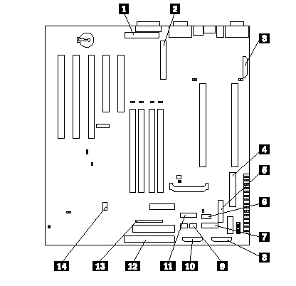
- Internal SCSI channel A (J29)
- Internal SCSI channel B (J17)
- Fan 3 (J35)
- Main Power (J4)
- Power (J51)
- Fan 1 (J59)
- 3.3V power for optional backplane (J52)
- Power system management (J12)
- DASD (SCSI) system management (J5)
- Fan 2 (J60)
- Operator information panel (J50)
- On-off / Reset panel (J38)
- IDE (J31)
- Diskette (J26)
System board external port connectors
The following illustration shows the external port connectors in the system board.
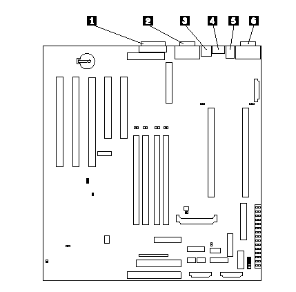
- Parallel port (J22)
- Video / Advanced System Management Process or port (J13)
- USB ports (J11)
- Ethernet ports (J9)
- Keyboard / mouse port (J6)
- Serial ports (J3)
System board switches and jumpers
The following illustration identifies the switches and jumpers on the system board.
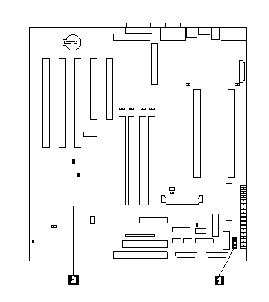
- System board switch block (SW1)
- Boot block jumper (J37)
System board jumper blocks
Any jumper blocks on the system board that are not shown in the illustration are reserved. For normal operation of the system, no jumpers should be installed on any of the jumper blocks.
System board switch block
The switch block contains microswitches 1-8. As shown in this illustration, switch 8 is at the top of the switch block and switch 1 is at the bottom. The following table describes each switch.
| Switch number | Description |
|---|---|
| 1- 4 | Microprocessor speed setting |
| 5 | Power-on override. When On, overrides the power-on switch and forces power-on mode. The system will always boot without the use of the power-on switch. The default setting is Off (disabled). |
| 6 | Clock frequency selection. When On, sets the host bus speed to 100 MHz. When Off, the host bus speed is 133 MHz. The default setting is Off. |
| 7 | Reserved. The default setting is Off. |
| 8 | Password override. When On, bypass the power-on password. When Off, require the user to enter the power-on password at startup, if one is set. The default setting is Off. |
| Microprocessor speed | Switch 1 | Switch 2 | Switch 3 | Switch 4 |
|---|---|---|---|---|
| 667/133 | On | On | Off | Off |
| 733/133 | On | Off | Off | Off |
| 800/133 | Off | On | On | On |
| 866/133 | Off | Off | On | On |
NOTE: The speed settings shown above apply only to unlocked processors. If the processors are production level they are locked and there is no need to change the speed settings.
System board LED locations
The following illustration identifies LEDs on the system board. You might need to refer to this figure when solving problems with the server.
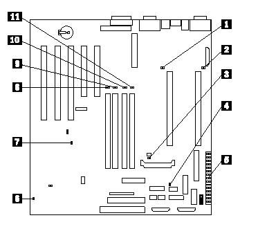
- Secondary microprocessor failure (CR7)
- Primary microprocessor failure (CR1)
- Voltage regulator module (VRM2) failure (CR16)
- Integrated voltage regulator (VRM1) failure (CR4)
- Diagnostics panel
- Advanced System Management Processor error (CR70)
- Power-on (CR56)
- DIMM1 failure (CR21)
- DIMM2 failure (CR28)
- DIMM3 ailure (CR18)
- DIMM4 failure (CR20)
Diagnostics panel LEDs
See the following table for a description of the diagnostics panel LEDs:
| CR | LED | Description |
|---|---|---|
| 29 | PS1 | Power supply 1 failure |
| 30 | PS2 | Power supply 2 failure |
| 31 | PS3 | Not used |
| 32 | NON | Non-redundant power |
| 33 | OVER | Overspecification. The system has exceeded the power capibilities of the installed power supply units. |
| 34 | NMI | Non-maskable interrupt occurred. |
| 22 | TEMP | System temperature exceeded maximum rating. |
| 23 | FAN | A fan failed or is operating slowly. |
| 24 | MEM | Memory failure. One or more dual in-line memory modules (DIMMS) failed. |
| 25 | CPU | Microprocessor failure. One or both microprocessors failed. |
| 26 | PCI 1 | Error on primary PCI channel (A) or system board. |
| 27 | PCI 2 | Error on secondary PCI channel (B) or system board. |
| 58 | VRM | Error on voltage regulator module or on integrated voltage regulator. |
| 53 | DASD1 | SCSI bus A failure. The SCSI backplane (if any) or a device connected to SCSI bus A failed. |
| 57 | DASD2 | SCSI bus B failure. The SCSI hot-swap disk drive backplane on SCSI bus B failed. |
Additional information
Netfinity 4500R - System service parts (FRU number) listing
Netfinity 4500R - Hardware Maintenance Manual
Document Location
Worldwide
Was this topic helpful?
Document Information
Modified date:
24 January 2019
UID
ibm1MIGR-52666