Product Documentation
Abstract
System board diagrams for the IBM BladeCenter HS20 (Type 8678)
Content
| System board illustration |
|---|
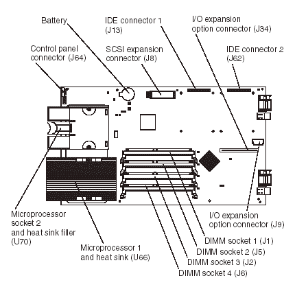
The following illustration shows the location of the system board components, including connectors for user-installable options.

Note: The SCSI expansion connector (J8) requires a terminator unless an expansion option is connected to it.
| System board LED locations |
|---|
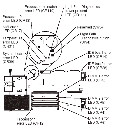
The following illustration shows the location of the LEDs on the system board. You might need to refer to this illustration when solving problems with the blade server. You need to remove the blade server from the BladeCenter unit, open the cover, and press the light path diagnostics button to light any error LEDs that were turned on during processing.
Note: Power is available to relight the light path diagnostics LEDs for a short period of time after the blade server is removed from the BladeCenter unit. During that period of time, you can relight the light path diagnostics LEDs for a maximum of 25 seconds (or less, depending on the number of LEDs that are lit and the length of time the blade server is removed from the BladeCenter unit) by pressing the light path diagnostics button. The light path diagnostics power present LED (CR111) lights when the light path diagnostics button is pressed if power is available to relight the blade-error LEDs. If the light path diagnostics power present LED does not light when the light path diagnostics button is pressed, no power is available to light the blade-error LEDs and they will be unable to provide any diagnostic information.

| Switches and jumpers |
|---|
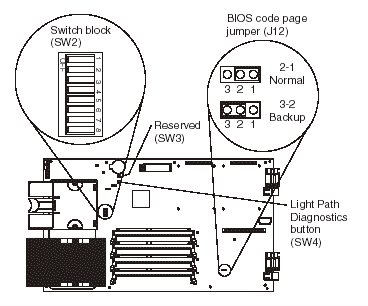
The following illustration shows the location of the switches and jumpers on the system board.

| Switches |
|---|
The following table describes the function of each switch on switch block (SW2).
Switch block (SW2)
| Switch number | Default value | Switch description |
|---|---|---|
| 1 through 4 | Off | Reserved |
| 5 | Off | Power-on override. When toggled to On, this switch forces the blade server to turn on, overriding the power-on button. The power-on override switch should be used for debug purposes only and should not be used to override management module control of the server. |
| 6 through 7 | Off | Reserved |
| 8 | Off | Power-on password override. Changing the position of this switch bypasses the power-on password check the next time the blade server is turned on and starts the Configuration/Setup Utility program so that you can change or delete the power-on password. You do not need to move the switch back to the default position after the password is overridden. See “Using passwords” in the Hardware Maintenance Manual (HMM) for additional information about the power-on password. |
Jumpers
When the BIOS code page jumper (J12) is moved from pins 1 and 2 to pins 2 and 3, you can start the blade server from a backup BIOS page (see “Recovering the BIOS code” in the HMM). The default position is pins 1 and 2.
Note: If you start the blade server from the backup page because the primary BIOS page has become damaged, you need to flash the primary BIOS code.
Document Location
Worldwide
Was this topic helpful?
Document Information
Modified date:
17 April 2023
UID
ibm1MIGR-55206