In the past with the POWER7 and POWER7+ based Scale-Out smaller Models, users had to shut down the whole server to add, remove, or replace an adapter safely. In fact, some servers would power off as you removed the lid.
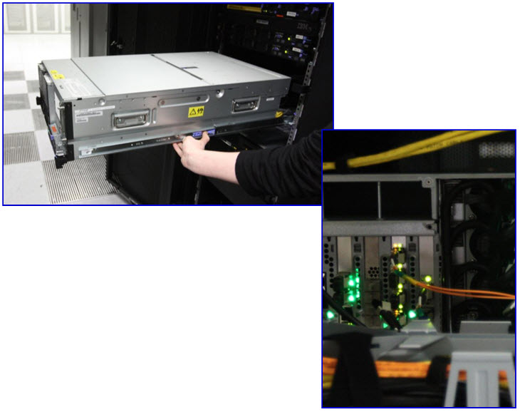
The powering-off disruption is no longer needed with the whole POWER8 and POWER9 PowerVM server range including the Scale-Out Models like the S822, S824, S922, and S924. These servers do not use the blind swap cassettes that allow the adapters to be removed from the rear of the server. So you must use a cable management arm setup to allow the server to be pulled out at the front on the rails. Then, you raise the lid and you find there are a number of items inside with Terracotta (reddish - orange) handles. These handles can be removed with the server running. Things like the fans and disks at the front of the server, internal I/O adapters, and power supplies at the back of the server.
BE WARNED - YOU MUST TO FOLLOW PROCEDURES ON THE HMC FIRST
These topics are covered in this article.
Note: Emily Barrett and Gareth Coates did all the work and screen captures. I (Nigel) did the editing of the results into this blog.
POWER8 Concurrent Maintenance (hot swap or hot-plug)
By Emily Barrett and Gareth Coates - EMEA Power Advanced Technology Support
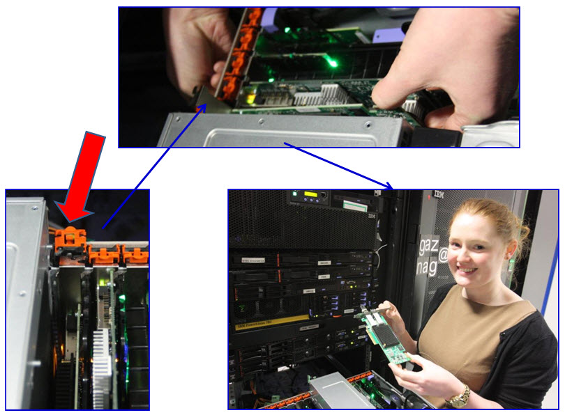
In the following picture, Emily is pointing to the rear of the POWER8 server, a Model S824 and at the PCIe3 adapter that needs to be replaced. It is powered on with LED lights showing it is active.
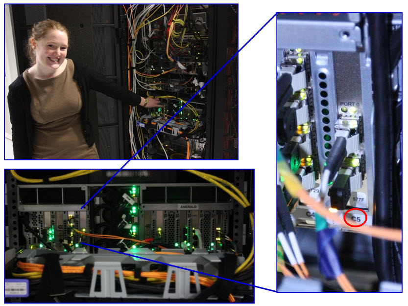
The previous picture (righthand side) shows the adapter slot is the label "C5". We need this information, when we access the Hardware Management Console (HMC) as we see in the following pictures, to start a procedure on that adapter slot.
The following pictures are from the HMC Enhanced+ graphical user interface.
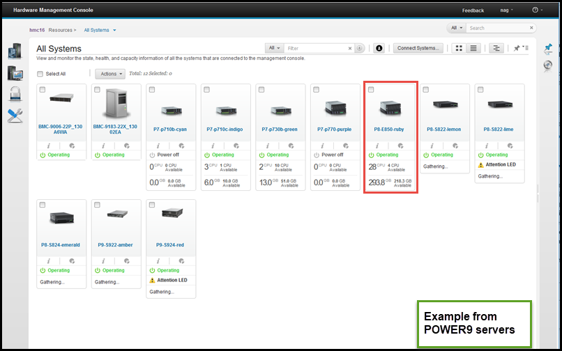
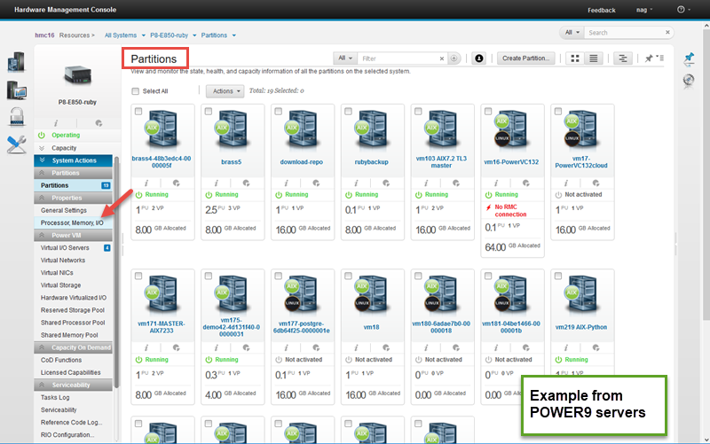
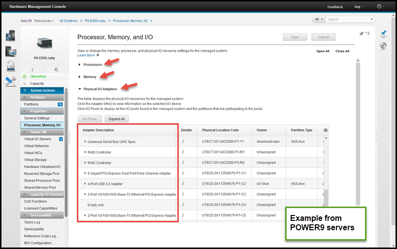
In the screen capture of the HMC, first the whole server is selected and then from the button the Properties pane selected, then
- "Processor, Memory, I/O"
- Click "I/O"
- And we can find the adapter ending in "C5" and in this case it is a "PCIe2 16 Gb 2-Port Fibre Channel Adapter"
Before we go further, the adapter has to be removed from the Logical Partition (LPAR) so that it is not active and no device drivers can be accessing it as it is being removed. Note: a Power Server Logical Partition is the same as a Virtual Machine (VM). In this case, the adapter is assigned to the Virtual I/O Server. So to investigate, the padmin user of the VIOS runs the lsdev command (the output fields is limited to the needed fields).
Log in to the VIOS as padmin user
$ lsdev -field name physloc | grep C5 fcs4 U78C9.001.WZS00DJ-P1-C5-T1 fcs5 U78C9.001.WZS00DJ-P1-C5-T2 fscsi4 U78C9.001.WZS00DJ-P1-C5-T1 fscsi5 U78C9.001.WZS00DJ-P1-C5-T2 hdisk0 U78C9.001.WZS00DJ-P1-C5-T1-W500507680210AC8C-L0 sfwcomm4 U78C9.001.WZS00DJ-P1-C5-T1-W0-L0 sfwcomm5 U78C9.001.WZS00DJ-P1-C5-T2-W0-L0
The adapter includes 2 external port, a number of device drivers running features and a Fibre Channel disk called hdisk0.
To illustrate what happens if you do not remove all these resources - let us try the HMC procedure to remove the device.
On the HMC, find the Field Replacement Unit (FRU) link.
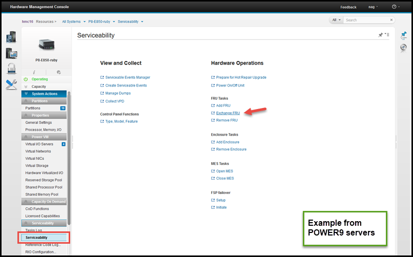
Whole Server view then:
- Serviceability
- Hardware
- Exchange FRU
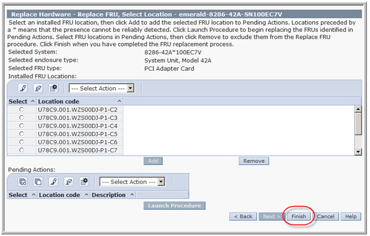
Then, as in the next picture, select the main server unit (if your server includes a remote I/O drawers) in which the adapter is found (the alternative would be a Remote I/O drawer unit) and then PCI adapter:
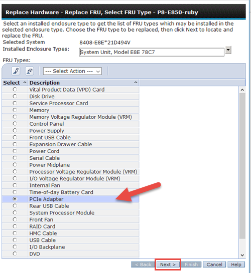
Then, click Next.
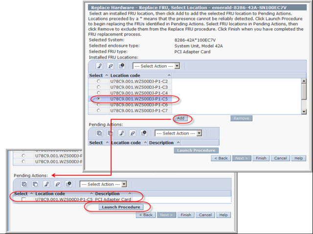
In the previous picture, the "C5" adapter slot position is selected and click Add. Then, click "Launch Procedure"
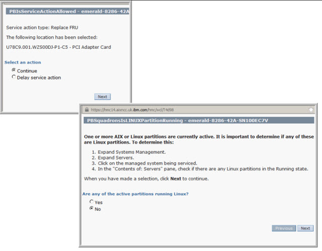
The HMC pane asks, do you want to do the operation now or later? Then, it wants you to check whether any LPAR involved is running Linux - in this case it is the Virtual I/O Server (VIOS), so the answer is "no" then, click Next.
In the following picture the HMC determines the PCIe3 adapter is still in use and needs you do fix that before proceeding:
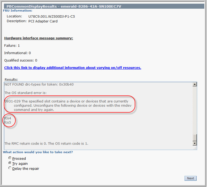
So next we go back to the VIOS and remove all the devices. This mechanism stops the VIOS from trying to use the device while or during the time the adapter is removed or a replacement is in the adapter slot.
On the VIOS LPAR
$ lspath status name parent connection Enabled hdisk0 fscsi0 500507680210ac8c,0 Enabled hdisk0 fscsi0 500507680220ac8c,0 Enabled hdisk0 fscsi4 500507680210ac8c,0 Enabled hdisk0 fscsi4 500507680220ac8c,0 $ $ $ rmdev -dev fcs4 -recursive sfwcomm4 deleted fscsi4 deleted fcs4 deleted $ $ rmdev -dev fcs5 -recursive sfwcomm5 deleted fscsi5 deleted fcs5 deleted $
The -recursive option makes sure that all related resources are also removed.
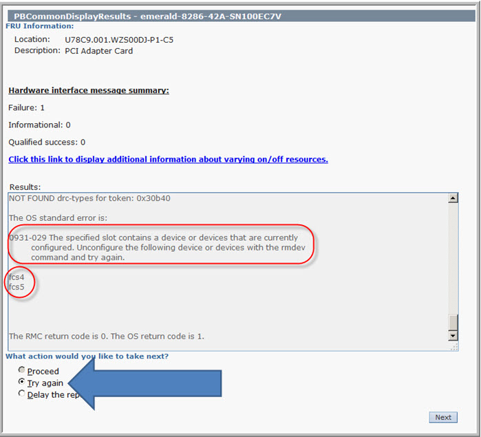
We return to the HMC, select the "Try Again" is selected and click Next. Read the two warning and information panes ...
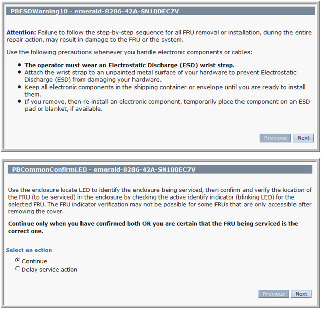
Making sure we change the correct adapter in the correct server.
The following picture shows the HMC via the service processor switches on the Identify LED at both the Server front "Ops Pane" and the read adapter slot.
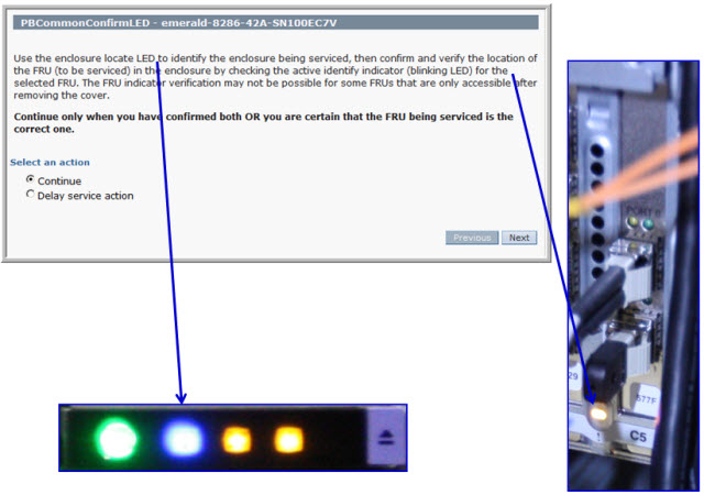
Important: Imagine a computer room with twenty racks of identical servers, it would be simple to go to the wrong rack, server, or adapter slot, so it is a good safety double check.
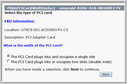
Next, we return to the HMC it wants to check the adapter width (single or double width). Double width adapters are rare. I guess it would want to power down both slots. So select "single slot" and Next.
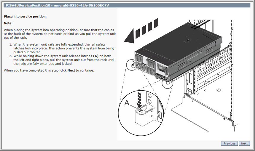
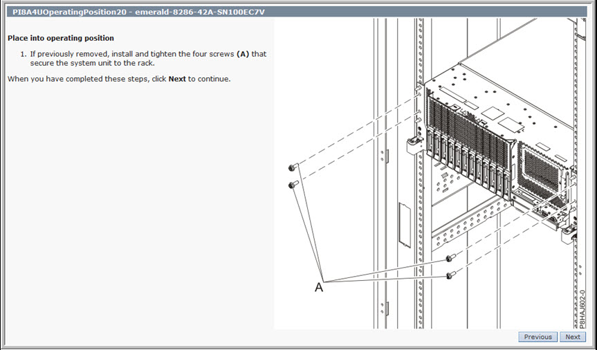
Then, the HMC gives you plenty of diagrams to find the correct adapter slot and how to unscrew the server and pull it out on the rails.
If you are sure you know the adapter slot and how to do that - click Next repeatedly to go through them, quickly:
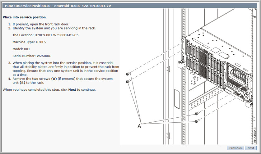
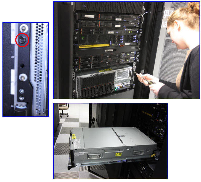
Opening the box
So Emily gets busy with the screwdriver, releases the server, and slides it out on the rails. I assumes the cable management arm is fitted at the back of the server and ALL that cables are using the arm.
It is worth checking the cabling, before pulling out the POWER8 server at the front and breaking all the cables or damage an adapter!
Nigel added: In the past, I've broken cables and you feel such an idiot afterward. The guys refused for years to let me move any RBG video screen!
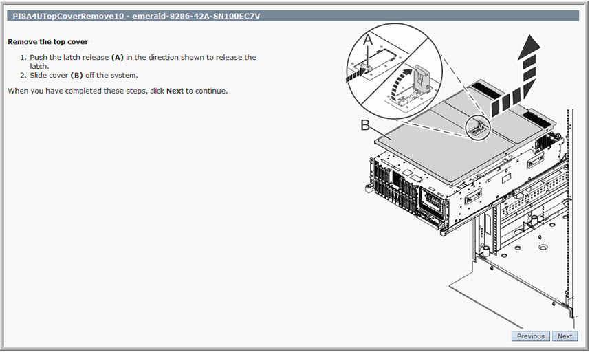
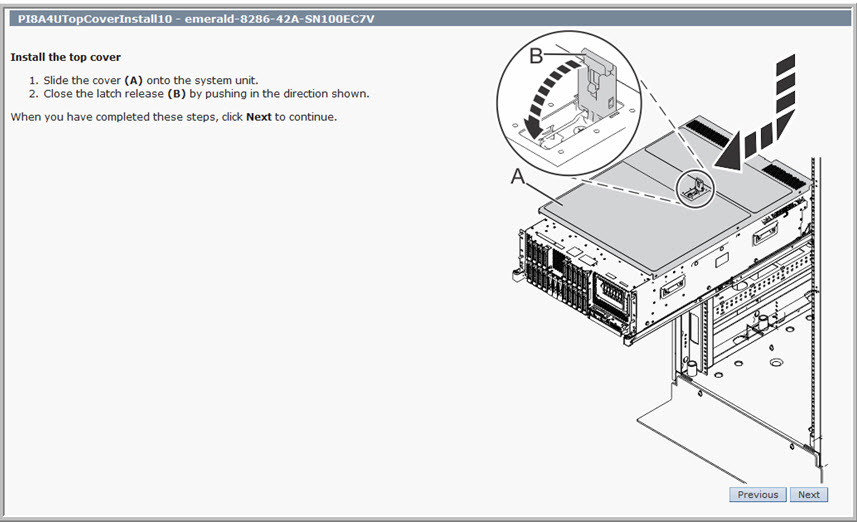
The HMC then informs you how to release and remove the server lid:
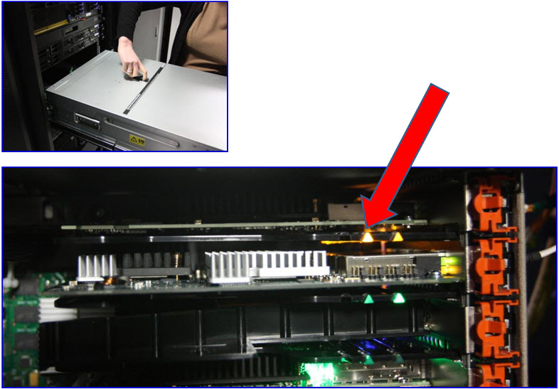
You guessed it! Emily does the same in the following picture and we can see the light path LED lit up next to the adapter. It would be a shame to yank out the wrong one out! Note the LED is a triangle "arrow" pointing at the adapter.
Removing the adapter
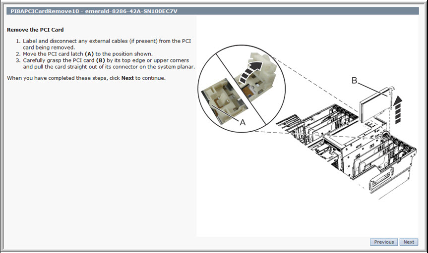
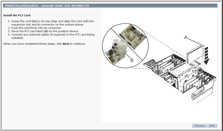
On the HMC, the following picture, it describes how to remove the adapter:
Oddly the diagram is removing the adapter from the same adapter slot as Emily. This coincidence is a nice touch from the hardware documentation editors. The picture shows a white click to release but it is really Red / Orange in colour. Emily carefully removes the adapter. This server is not a $10 PC Ethernet NIC adapter but a rather expensive super fast enterprise-level adapter so treat it with care. You can't quite see it but near Emily's elbow she is wearing an approved electrostatic earth strap that is also clipped to the frame of the rack.
At last, the job is done - - - well - - - not quite. This task is to replace the adapter with another one (you might guess we are going to put the same adapter back in the slot for this practice run). Alternative tasks are"Add Adapter" or a "Remove Adapter" but I hope you get the idea.
Finishing off
The HMC informs you how to finish off using the reverse procedure:
Emily points out the blue little arm clips you raise to release the drawer so it can be slid back into the rack, in following pictures and the adapter is showing LEDs.
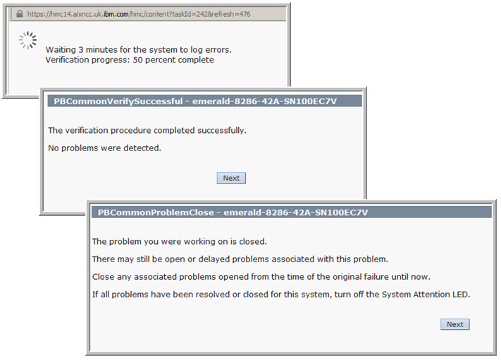
In the following pictures, the HMC plays it safe and waits a bit to let the adapter power on and completes the initialisation functions.
If we are happy, we can close the "Replace Hardware" Task as in the following pictures:
Back on the Operating System, here the VIOS, we tell it to investigate its buses for new I/O adapters.
Note: the AIX the command is "cfgmgr" and on Linux it is more complicated (IMHO), so check you Linux documentation.
Back on the VIOS as the padmin user
$ cfgdev $ lspath status name parent connection Enabled hdisk0 fscsi0 500507680210ac8c,0 Enabled hdisk0 fscsi0 500507680220ac8c,0 Enabled hdisk0 fscsi4 500507680210ac8c,0 Enabled hdisk0 fscsi4 500507680220ac8c,0 $
The adapter and associated devices are ready to use again. Once you perform this or similar tasks a few of times, it is very simple to follow but the HMC does guide you and makes sure you don't miss a step.
- - - The End - - -