Troubleshooting
Problem
Adding an adapter, such as a communication adapter, extends the capabilities and power of your server.
Resolving The Problem
Adding an adapter, such as a communication adapter, extends the capabilities and power of your server. For example, you can add a redundant array of independent disks (RAID) adapter that can enhance logical-drive capacity and performance.
Adapter considerations
Your Netfinity 5000 supports ISA and PCI adapters. You can install up to six adapters in the connectors on the system board.
The system board in your server contains 16-bit, ISA-bus expansion connectors and 32-bit, PCI-bus expansion connectors. One of the expansion slots is a shared PCI/ISA slot. One of the expansion slots supports only ISA adapters. The remaining four slots support only PCI adapters. Your server supports only 5.0 volt adapters on the PCI bus.
NOTES:
- You can install PCI adapters in slots 1 5. Slots 1-4 are on PCI bus 1, slot 5 is on PCI bus 0. Both PCI buses are primary buses; when the system scans the buses to see what devices are on them, it scans PCI bus 0 first.
- You can install ISA adapters in the slots 1 and 2.
NOTE: If an ISA adapter is not a Plug and Play device, you must allocate the system resources that the adapter will use. Use the Plug and Play choice in the Advanced Setup selection of the Configuration/Setup Utility program to allocate resources.
The following figure shows the location of the PCI and ISA expansion slot connectors on the system board.
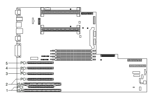
NOTE: Expansion slots 1 and 2 are shared slots. A shared slot can be used by an adapter installed in either the PCI connector or the adjacent ISA connector, but not both.
Your server comes with a video controller. This video controller is an integrated component on the system board. It is not in an expansion slot. The integrated video controller has super video graphics array (SVGA) technology.
The integrated video controller is not removable. If you want to disable this controller and use a video adapter instead, you can install a video adapter in an expansion slot. When you install a video adapter, the server BIOS automatically disables the integrated video controller.
Attention: To avoid possible damage to adapters and server components, be sure that the adapters you install do not touch each other or the other components (such as the microprocessor) inside the server.
Installing or removing adapters
This section describes the procedure for installing an adapter. If you want to remove an adapter, reverse the following steps.
Before you begin:
- Read Safety Information.
- Read the documentation that comes with the option.
- Review the instructions that come with the adapter to determine if the adapter must be installed in a certain slot; otherwise, use any available, bus-compatible slot.
NOTE: If you install a video adapter, the server automatically disables the video controller on the system board. IBM recommends that the video be installed in slot 5.
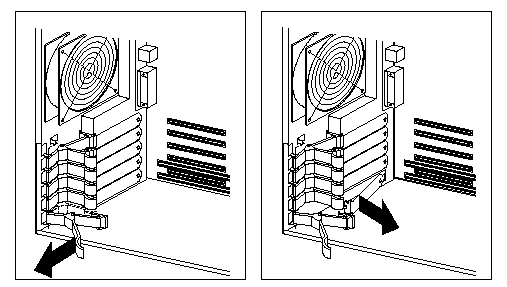
- If you have not done so, remove the server cover. See "Option Installation" in the HMM.
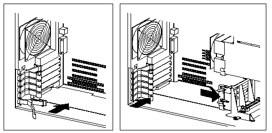
- Remove the expansion-slot cover.
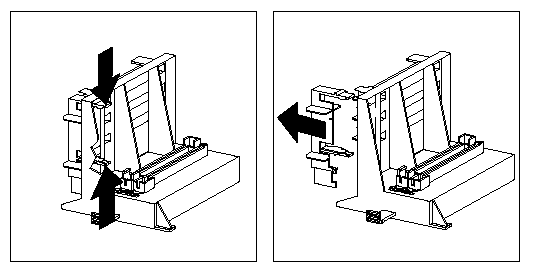
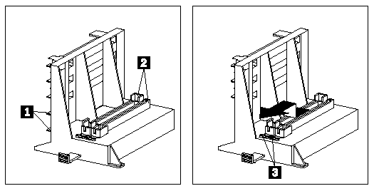
- Release the slot retaining clamp by pulling the curved arm on the clamp away from the system board.
NOTE: The slot retaining clamp might differ slightly from the clamp in this illustration.
-
- Remove the expansion-slot cover from the slot opening.
- If the adapter is a full-length card, continue with this step. Otherwise, go to step 5.
a. Remove the card support bracket retaining clip.
b. If the adapter is a full length card in slot 1 or 2, ensure that the card support bracket has the appropriate card support installed for that slot.
Each card support is also identified on the tab as listed in the following table:
| Card type | Card support color |
|---|---|
| ISA | Black |
| PCI | White |
NOTE: You may find it easier to replace the card support with the appropriate color card support if you remove the card support bracket from the server first.
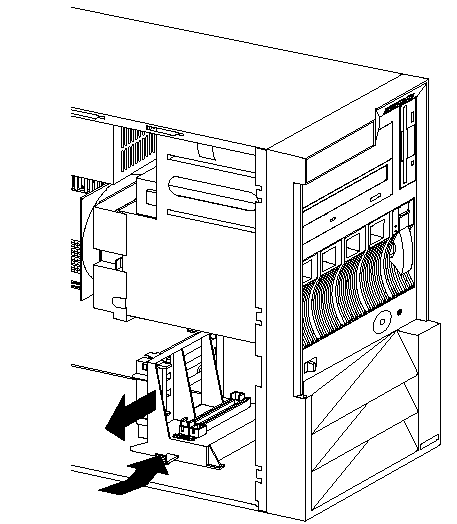
- To remove a card support from a slot 1 or storage location 2, gently release the card support tab 3 and slide the card support away from the system board until the card support is free.
- To insert a card support in a slot or a storage location, place the card support in the slot or storage opening and slide the card support toward the system board until the tab clicks into place. If you removed the card support bracket from the server, replace it in the server now.
- Touch the static-protective package to any unpainted metal surface on the server; then, remove the adapter from the package.
- Install the adapter:
- Carefully grasp the adapter and align it with the expansion slot (and with the card support bracket if a full-length adapter).
- Press the adapter firmly into the connector until fully seated.
- Fit the foot of the slot retaining clamp to the top of the expansion slot.
- Push the curved arm of the slot retaining clamp toward the adapter until the clamp is locked into place.
- If necessary, connect any internal cables to the adapter. Refer to the documentation that comes with the option.
- If you removed the card support bracket retaining clip in step 4a, reinstall it now.
- If you want to install or remove any other options, do so now. Otherwise, refer to "Completing the Installation" in the HMM.
Document Location
Worldwide
Was this topic helpful?
Document Information
Modified date:
23 January 2019
UID
ibm1DDSE-426S67