Product Documentation
Abstract
System board diagrams - IBM System x3500 (Type 7977)
Content
| System-board internal connectors and switches | |
| System-board LEDs | |
| System-board external connectors | |
| SAS backplane | |
| Related information (HMM) |
The following illustration shows the internal connectors on the system board:
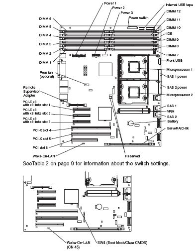
| Switch number | Switch description |
|---|---|
| 1 | Boot block:
|
| 2 | Clear CMOS:
|
Notes:
1. Before you change any switch settings or move any jumpers, turn off the server; then, disconnect all power cords and external cables.
2. Any system-board switch or jumpers blocks that are not shown in the illustrations in this document are reservered.
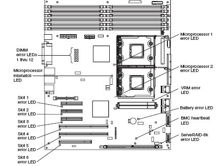
The following illustration shows the switches and LEDs on the system board:
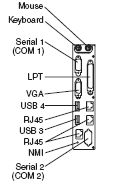
The following illustration shows the external input/output connectors and the NMI switch on the system board:
| Back to top |
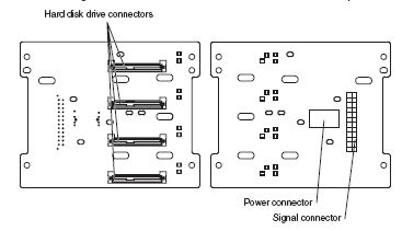
The following illustration shows the connectors on the SAS backplane:
| Back to top |
| Problem Determination and Service Guide - IBM System x3500 (Type 7977) |
Document Location
Worldwide
Was this topic helpful?
Document Information
Modified date:
24 January 2019
UID
ibm1MIGR-5070452