Product Documentation
Abstract
System board diagrams for the IBM eServer 326.
Content
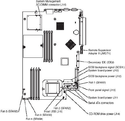
System-board internal connectors
The following illustration shows the internal connectors on the system board:
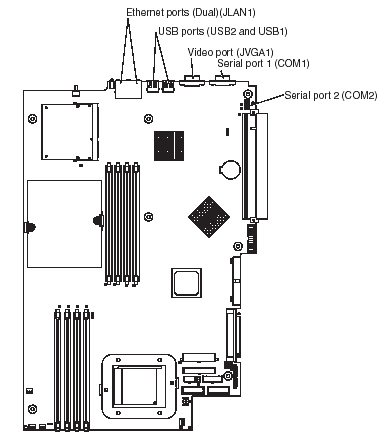
System-board external connectors
The following illustration shows the external input/output connectors (ports) on the system board:
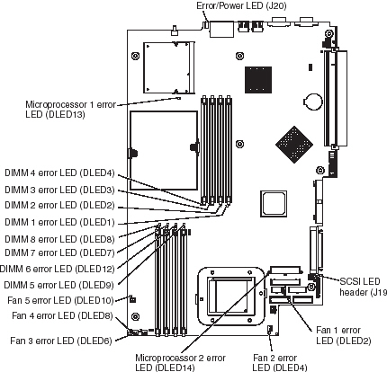
System-board LEDs
The following illustration shows the light-emitting diodes (LEDs) on the system board.
Note: For more information about the system-board LEDs, see the Hardware Maintenance Manual and Troubleshooting Guide.
System-board option connectors
The following illustration shows the connectors on the system board for user-installable options:
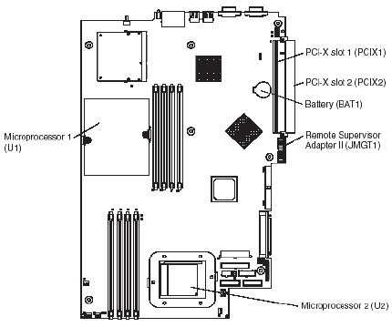
Note: The VRMs for the microprocessors are on the system board.
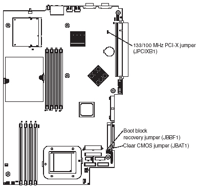
System-board switches and jumpers
The following illustration shows the switches and jumpers on the system board. Any jumper blocks on the system board that are not shown in the illustration are reserved. See the section about recovering the basic input/output system (BIOS) code in the Hardware Maintenance Manual and Troubleshooting Guide about the boot block recovery jumper.
Document Location
Worldwide
Was this topic helpful?
Document Information
Modified date:
24 January 2019
UID
ibm1MIGR-57578