How To
Summary
This document provides step-by-step procedures to set up an existing Db2 HADR configuration with Pacemaker on Google Cloud (GC) with virtual IP (VIP) addresses. VIPs establish communication between the Db2 database and the application and are routed by the Google Cloud Internal Load Balancer.
Objective
The internal passthrough Network Load Balancer service with failover support routes the client traffic to the primary database in an Db2 HADR cluster.
GC passthrough Network Load Balancers use virtual IP (VIP) addresses, backend services, instance groups, and health checks to route the traffic. The Pacemaker cluster is configured to use the GC Load Balancer resource agent to respond to health checks to manage the transparent connection and failover to the Db2 databases in the cluster.
Note:
You have a Virtual Private Cloud network on Google Cloud. For instructions on configuring a VPC network and firewall rules, and instructions for setting up a NAT gateway or bastion host see: VPC networks | Google Cloud.
To get more information on the internal Load Balancer, refer to: Internal passthrough Network Load Balancer overview | Load Balancing | Google Cloud.
The following figure shows a high-level overview of a 2-node Db2 HADR setup with virtual IP address. Clients access the database through the virtual IP address.
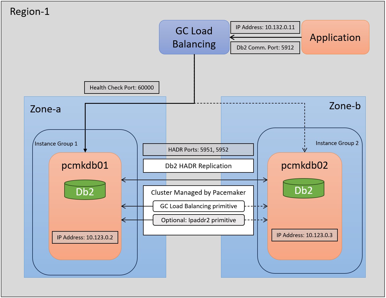
In this document, we use two virtual machines in the cluster:
The hostnames of the machines are pcmkdb01 and pcmkdb02 and the HADR cluster is already set up and uses the ports 5951 and 5952 for communication between the HADR primary and standby databases. The Google Load Balancer uses the IP address 10.132.0.11.
The network traffic that is targeted for this IP address is redirected to either hosts pcmkdb01 or pcmkdb02 that are assigned to two GC instance groups.
The two instance groups must exist only once for the cluster. You need to create objects like GC Load Balancer, GC Health Check, and the Pacemaker resources for load balancing for each virtual IP address.
The Google Load Balancer checks the availability of the hosts on port 60000 in our example. The Pacemaker cluster resource of type “gcp-ilb” responds to this request.
The configuration of the Pacemaker cluster ensures that this resource is running only once for a database and health check port and so network traffic is always redirected to one of the hosts. The application with a Db2 client communicates through the IP address 10.132.0.11 that acts as a virtual IP address.
Note:
The example describes how to set up a virtual IP address for a primary database in a Pacemaker cluster that contains one HADR pair only. If you are running multiple databases in the cluster, you need to set up a Google Load Balancer and the “gpc-ilb” Pacemaker resource for each database and you need to specify a different and unique port number. If you want to add a virtual IP address for the standby database, you also need a dedicated Load Balancer with a unique port number and name. However, Google Cloud Instance Groups exist only once for the whole cluster.
Environment
This document describes the optional feature of using a VIP connection.
As a prerequisite, make sure that you already did set up the Db2 HADR cluster. Also, make sure that you created the Db2 integrated Pacemaker cluster manager and that you configured Pacemaker resources for the Db2 instance and its databases. Refer to the “Configuring high availability with the Db2 cluster manager utility (db2cm)” page of the IBM Documentation to deploy the automated HADR solution: Configuring high availability with the Db2 cluster manager utility (db2cm) – IBM Documentation.
The restrictions in the IBM Documentation page apply here: Restrictions on Pacemaker - IBM Documentation.
As a prerequisite, the virtual machines in the cluster must reside in the same region but can reside in different zones to increase the resiliency of the cluster. Also, the virtual IP address used must reside in the same region as the nodes in the cluster.
In addition, make sure that the GC guest environment is available on all nodes in the cluster.
This guest environment is automatically deployed with each Google-provided public image and is set up automatically.
If you are using a custom image, ensure that the guest environment is set up according to the following documentation: Guest environment | Compute Engine Documentation | Google Cloud.
In addition, you need to launch GC Cloud Shell and authorize the gcloud utility. This process is described here: Launch Cloud Shell | Google Cloud.
To be able to set up the pacemaker cluster with VIP addresses, it is beneficial to follow a consistent namespace for the different components.
In our case, the names of the entities are derived from the hostnames in the cluster, the Db2 instance, and database name in the cluster. In this document, we use placeholders for the entities that you need to replace with the entities in your environment. For every database with a primary or secondary virtual IP address you need to create a Google Load Balancer with a unique name and port.
Steps
Compile a list of all host names, including virtual host names, and update your DNS servers to enable proper IP address to host-name resolution. If a DNS server doesn't exist or you can't update and create DNS entries, you need to use the local host files. Make sure to include all the individual virtual machines that are participating in this scenario. For an introduction to DNS, refer to: Internal DNS | Compute Engine Documentation | Google Cloud
| Entity | Name |
|---|---|
| Google Cloud Project | db2pcmk |
| Google Cloud Region | europe-west1 |
| Google Cloud Zone | europe-west-1b |
| Google Cloud VPC | Default |
| Google Cloud Subnet | Default |
| Db2 Instance | db2gp1 |
| Db2 database | GP1 |
| Hostname/tag of cluster node 1 | pcmkdb01 |
| Hostname/tag of cluster node 2 | pcmkdb02 |
| IP address cluster node 1 | 10.132.0.2 |
| IP address cluster node 2 | 10.132.0.3 |
| Hostname for virtual IP address | db2gp1gp1pvip |
| Virtual IP | 10.132.0.11 |
| Google Cloud virtual IP address | db2gp1-gp1-primary-vip |
| Google Cloud health check | db2gp1-gp1-primary-hc |
| Port number for the Google Cloud health check | 60000 |
| Google Cloud firewall rule | db2gp1-gp1-primary-fwall |
| Google Cloud first instance group | db2pcmk-db2pcmkdb01-group |
| Google Cloud second instance group | db2pcmk-db2pcmkdb02-group |
| Google Cloud Load Balancer backend | db2gp1-gp1-primary-ilb |
| Google Cloud forwarding rule | db2gp1-gp1-primary-rule |
| Pacemaker Cluster | |
| Pacemaker Load Balancer resource | db2_db2gp1_db2gp1_GP1-primary-lbl |
| Pacemaker Load Balancer colocation constraint | col_db2_db2gp1_db2gp1_GP1_primary-lbl |
| Pacemaker Load Balancer order rule | ord_db2_db2gp1_db2gp1_GP1_primary-lbl |
| Pacemaker VIP resource | db2_db2gp1_db2gp1_GP1-primary-VIP |
| Pacemaker VIP collocation constraint | col_db2_db2gp1_db2gp1_GP1_primary-VIP |
| Pacemaker VIP order rule | ord_db2_db2gp1_db2gp1_GP1_primary-VIP |
gcloud compute instance-groups unmanaged create db2pcmk-db2pcmkdb01-group --zone=europe-west1-b
gcloud compute instance-groups unmanaged add-instances db2pcmk-db2pcmkdb01-group --zone=europe-west1-b --instances=pcmkdb01
gcloud compute instance-groups unmanaged create db2pcmk-db2pcmkdb02-group --zone=europe-west1-b
gcloud compute instance-groups unmanaged add-instances db2pcmk-db2pcmkdb02-group --zone=europe-west1-b --instances=pcmkdb02
You must create the instance groups only once for your HADR Cluster. The instance groups are used for all load balancers and virtual IP addresses used in the cluster.
In Cloud Shell, reserve and validate an IP address for each primary or standby database in the cluster.
gcloud compute addresses create db2gp1-gp1-primary-vip --project=db2pcmk2023 --addresses=10.132.0.11 --region=europe-west1 --subnet=default
In Cloud Shell, create and validate the health checks. To avoid conflicts with other services, designate a free port from the private range, 49152-65535. The check-interval and timeout values are adopted to increase failover tolerance during Compute Engine live migration events. You can adjust the values, if necessary.
gcloud compute health-checks create tcp db2gp1-gp1-primary-hc --port=60000 --proxy-header=NONE --check-interval=10 --timeout=10 --unhealthy-threshold=2 --healthy-threshold=2
Refer to the following documentation on network tags: Add network tags.
gcloud compute instances describe pcmkdb01 --format='table(name,status,tags.list())'
gcloud compute instances describe pcmkdb02 --format='table(name,status,tags.list())'
gcloud compute firewall-rules create db2gp1-gp1-primary-fwall --network=default --action=ALLOW --direction=INGRESS --source-ranges=35.191.0.0/16,130.211.0.0/22 --target-tags=pcmkdb01,pcmkdb02 --rules=tcp:60000
If you have multiple virtual IP addresses in your cluster, you can optionally create one single firewall rule for the complete cluster and add each Health Check Port to this firewall rule. This approach reduces the number of firewall rules but can decease clarity of the setup. Therefore, in this document, we use a dedicated firewall rule for each virtual IP address and we incorporated the database name and the HADR role in the firewall rule naming. The following example updates an existing firewall rule with the two ports 60000 and 60020.
gcloud compute --project=db2pcmk2023 firewall-rules update db2gp1-gp1-primary-fwall --rules=tcp:60000,tcp:60020
In Cloud Shell, create an internal network Load Balancer and add both Compute Engine instance groups as a backend to the Load Balancer.
Note: One of the Compute Engine instance groups need to be specified as a failover group.
gcloud compute backend-services create db2gp1-gp1-primary-ilb --load-balancing-scheme internal --health-checks db2gp1-gp1-primary-hc --no-connection-drain-on-failover --drop-traffic-if-unhealthy --failover-ratio 1.0 --region europe-west1 --global-health-checks
gcloud compute backend-services add-backend db2gp1-gp1-primary-ilb --instance-group db2pcmk-db2pcmkdb01-group --instance-group-zone europe-west1-b --region europe-west1
gcloud compute backend-services add-backend db2gp1-gp1-primary-ilb --instance-group db2pcmk-db2pcmkdb02-group --instance-group-zone europe-west1-b --failover --region europe-west1
gcloud compute forwarding-rules create db2gp1-gp1-primary-rule --load-balancing-scheme internal --address 10.132.0.11 --subnet default --region europe-west1 --backend-service db2gp1-gp1-primary-ilb --ports ALL
To do so, on both virtual machines in the cluster use the socat utility to respond to the health check.
To manually respond to the health check, execute as user root:
timeout 60s socat - TCP-LISTEN:60000,fork
gcloud compute backend-services get-health db2gp1-gp1-primary-ilb --region europe-west1 | grep 'healthState:\|ipAddress:'
healthState: UNHEALTHY
ipAddress: 10.132.0.2
healthState: HEALTHY
ipAddress: 10.132.0.3
To do so, the Load Balancer resource of type ‘gcp-ilb’ needs to be created. The resource listens and responds to the GC health check and enables the GC backend to redirect the network traffic to the right node in the cluster. Repeat this step for each database in the cluster that needs to be reachable through the GC Load Balancer and a VIP. The resource will be part of an order rule and collocation constraint and started after the configuration is completed.
db2cm -create -gc -primarylbl 60000 -db GP1 -instance db2gp1
In this setup, the communication between any cluster node itself and the virtual IP addresses are always routed to the node itself in a local loopback.
systemctl stop google-guest-agent
[IpForwarding]
ethernet_proto_id = 66
ip_aliases = true
target_instance_ips = false

[NetworkInterfaces]
dhclient_script = /sbin/google-dhclient-script
dhcp_command =
ip_forwarding = false
setup = true
db2cm -create -gc -primaryVIP 10.132.0.11 -db GP1 -instance db2gp1
Additional Information
db2cm -delete -gc -primaryVIP -db GP1 -instance db2gp1
Once you made the change, reboot both servers to clean up and activate the change.
db2cm -delete -gc -primarylbl -db GP1 -instance db2gp1
Document Location
Worldwide
Was this topic helpful?
Document Information
Modified date:
14 November 2023
UID
ibm17071284