Troubleshooting
Problem
IBM Power Systems Hardware Management Consoles (HMCs) have several physical status and fault LEDs. This document describes the meaning of each LED on each model and what, if any, actions are needed when one is lit.
For System Attention LEDs on IBM Power Systems managed by HMCs, see Troubleshooting the amber System Attention LED or indicator on IBM Power Systems instead.
Diagnosing The Problem
Select your model of HMC in this list to see information about fault and status LEDs on that model.
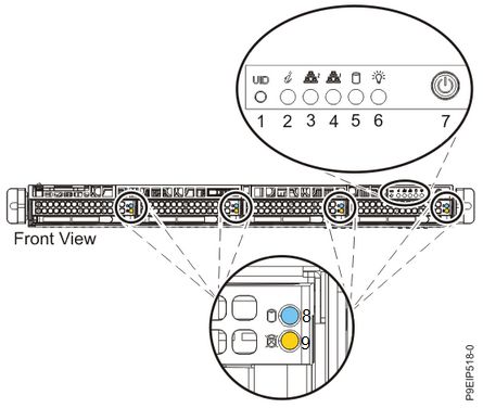
7063-CR2
Front of HMC:
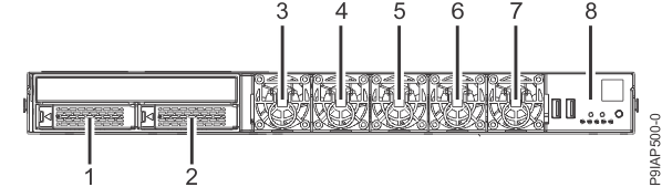
1 - Disk drive 0
2 - Disk drive 1
3, 4, 5, 6, 7 - Fans 0-4, respectively.
8 - Control panel
Control panel:
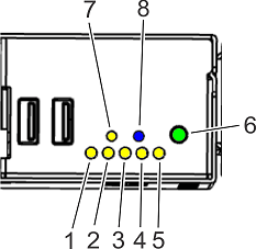
1, 2, 3, 4, 5 - Fan fault (amber) for fans 0-4, respectively.
6 - Power button and power status LED (green):
- Off - No AC power is present or the BMC is not booted yet.
- Flashing - The BMC is booted, but the HMC is powered off.
- Solid - The HMC is powered on.
7 - System fault LED (amber) - Lights when the HMC has any hardware fault.
8 - Identify LED (blue). For more information about this LED, see Identifying the 7063-CR2 that needs servicing.
Disk drives:
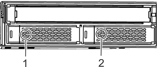
1 - Disk drive 0
2 - Disk drive 1
Each disk drive has two LEDs:
- Power status (green) - On when the drive is powered on.
- Activity (amber) - Flashes when the drive has activity.
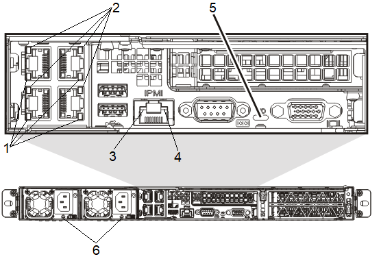
Rear of HMC:
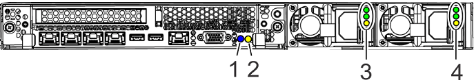
1 - Identify LED (blue). This LED is a mirror of the Identify LED on the front of the HMC.
2 - System fault LED (amber). This LED is a mirror of the System fault LED on the front of the HMC.
3 and 4 - Power Supply LEDs:
- Top - AC power (green) lights solid when valid AC power is connected to the power supply.
- Middle - DC power (green):
- Flashing when AC power is attached but the HMC is powered off
- Solid when the power supply is powered on.
- Bottom - Power fault (amber).
7063-CR1
Front of HMC:
1 - UID button
2 - Identify LED (blue/red) can be in one of these states:
-
Solid blue indicates that the UID button (1) was pressed.
-
Flashing blue indicates that the ipmitool chassis identify command was used. For more information, see Identifying the 7063-CR1 that needs servicing.
-
Solid red indicates that the HMC is overheated.
-
Flashing red at 1 Hz indicates that a fan failed.
-
Flashing red at 0.25 Hz indicates that a power supply failed.
3 and 4 - The network activity LEDs (green) flash when there is network activity on the four Ethernet ports.
5 - SATA drive activity (amber) flashes when there is hard disk activity.
6 - Power status (green) lights solid when the HMC is powered on.
7 - Power button.
8 - Disk drive activity LED (blue) flashes when there is activity on the disk.
9 - Disk drive status LED (red) - Not used on this model.
Rear of HMC:
1 - HMC Ethernet link LED:
- Green for 10Gbps link
- Amber for 1Gbps link
- Off (not lit) for 100Mbps link
2 - HMC Ethernet activity LED (yellow) flashes to indicate network activity.
3 - BMC Ethernet link LED
4 - BMC Ethernet activity LED (yellow) flashes to indicate network activity
5 - Identify LED (blue/red) - This LED is a mirror of the Identify LED from the front of the HMC.
6 - Power supply LED (green/amber):
- Steady green - power is on
- Flashing green - AC power is connected, but the HMC is not powered on
- Steady amber - power is off, or a power fault occurred
- Flashing amber - the power supply is overheating
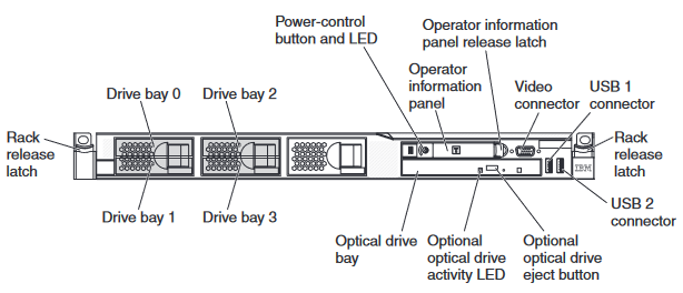
7042-CR9
Front of HMC:
The optical drive activity LED lights and flashes when the DVD drive is in use.
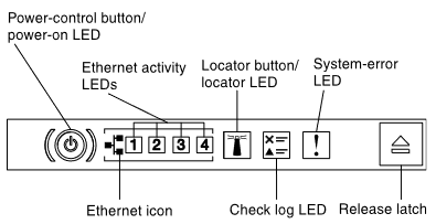
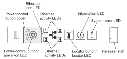
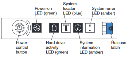
Operator information panel:
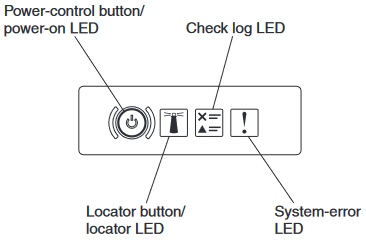
Power-on LED (green):
- Not lit: AC power is not present.
- Flashing rapidly (4 times per second): AC power is present, but the HMC is not ready to be powered on. The power-control button is disabled. This lasts approximately 1 to 3 minutes after AC power is connected.
- Flashing slowly (once per second): AC power is present, and the HMC is ready to be powered on.
- Solid: HMC is powered on.
System Locator LED (blue): Not used on this model.
Check log LED (yellow): A noncritical event occurred with the HMC hardware. See the Error listing on the LCD operator panel assembly.
System-error LED (yellow): A system error occurred. View the Error information on the LCD operator panel assembly.
LCD operator panel assembly:
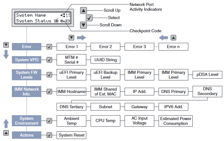
To view Error information, use the up or down arrow buttons to select "Error", then press the checkmark button to cycle through the error details.
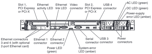
Rear of HMC:
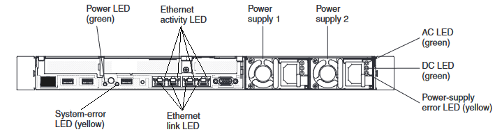
Power LED (green) and System-error LED (yellow): These LEDs are mirrors of the LEDs with the same name from the front of the HMC.
Ethernet link LEDs: When these LEDs are lit, they indicate that there is an active link connection on the 10BASE-T, 100BASE-TX, or 1000BASE-TX interface for the Ethernet port.
Ethernet activity LEDs: When these LEDs are lit, they indicate that the server is transmitting to or receiving signals from the Ethernet LAN that is connected to the Ethernet port.
AC LED (green): Lit solid when the power supply is receiving AC power.
DC LED (green): Flashes with the HMC is turned off. Lights solid when the HMC is turned on. If the HMC is turned on and this LED is flashing, either the power supply is not receiving valid AC power or there is a problem with the power supply or the system board.
Power-supply error LED (yellow): Lights solid when there is a fault inside the power supply.
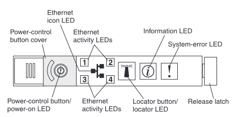
7042-CR8
Front of HMC:
The optical drive activity LED lights and flashes when the DVD drive is in use.
Operator information panel:
Power-on LED (green):
- Not lit: AC power is not present.
- Flashing rapidly (4 times per second): AC power is present, but the HMC is not ready to be powered on. The power-control button is disabled. This lasts approximately 1 to 3 minutes after AC power is connected.
- Flashing slowly (once per second): AC power is present, and the HMC is ready to be powered on.
- Solid: HMC is powered on.
Ethernet Activity LEDs (green): When any of these LEDs are lit, there is network activity on the indicated Ethernet port on the rear of the HMC.
System Locator LED (blue): Not used on this model.
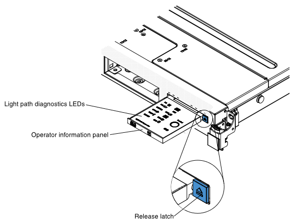
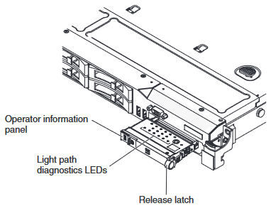
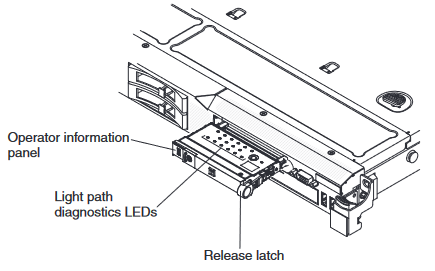
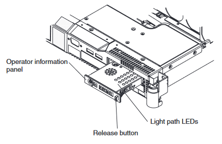
Information LED (yellow): A noncritical event occurred with the HMC hardware. Slide the Release latch to open the Light Path Diagnostic Panel and see which LED is lit. Also, see the POST error logs in the BIOS setup menu to learn more.
System-error LED (yellow): A system error occurred. Slide the Release latch to open the Light Path Diagnostic Panel and see which LED is lit.
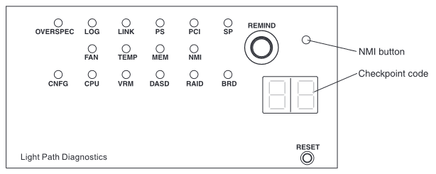
Light path diagnostics panel:
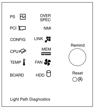
PS: A power supply has an error. If the CONFIG LED is also lit, the power supply configuration is invalid. Check the power supply with a yellow LED lit on the rear of the HMC. Make sure both power supplies are seated correctly and connected to valid AC power of the same voltage. Replace the failed power supply.
OVER SPEC: The power supplies are supplying more power than their maximum rating. Replace the failing power supply or remove optional devices from the HMC.
PCI: An error occurred on a PCI card, a PCI bus, or on the system board. An additional LED is lit next to a failing PCI slot. Check the system error log for information about the error. If you cannot isolate the problem, remove one PCI device at a time, restarting the HMC after adapter each removal.
NMI: A machine check error occurred or the NMI button was pressed. Check the system error log for information about the error. Restart the HMC.
CONFIG: A hardware configuration error occurred. If the PS LED is lit, the power supply configuration is invalid. If the CPU LED is lit, check the microprocessor options for compatibility. If the MEM LED is lit, check the memory DIMM options and placement for compatibility.
LINK: Not used on this model.
CPU: There is a problem with a microprocessor. Ensure the microprocessor is installed correctly and is compatible.
MEM: A memory error occurred. Replace the failing DIMM indicated by the lit LED on the system board.
TEMP: The HMC temperature exceeded a threshold level. Ensure the room temperature is not too warm. Ensure the front and rear air vents are not blocked. If a fan failed, replace the failed fan.
FAN: A fan failed, is operating too slowly, or was removed. A failing fan can also cause the TEMP LED to be lit. Replace the failing fan, which is indicated by a lit LED near the fan connector on the system board.
BOARD: An error occurred on the system board. Check the LEDs on the system board to identify the component that is causing the error. Check the system error log for information about the error. The Time Of Day battery may be low. Replace the Time Of Day battery. Replace the system board.
HDD: A hard disk drive error occurred. Check the LEDs on the hard disk drives and replace the indicated drive.
Rear of HMC:
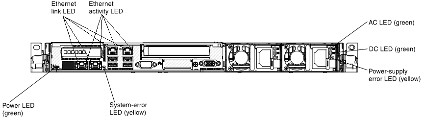
Power LED (green) and System-error LED (yellow): These LEDs are mirrors of the LEDs with the same name from the front of the HMC.
AC LED (green): Lit solid when the power supply is receiving AC power.
DC LED (green): Flashes with the HMC is turned off. Lights solid when the HMC is turned on. If the HMC is turned on and this LED is flashing, either the power supply is not receiving valid AC power or there is a problem with the power supply or the system board.
Power-supply error LED (yellow): Lights solid when there is a fault inside the power supply.
Ethernet link LEDs: When these LEDs are lit, they indicate that there is an active link connection on the 10BASE-T, 100BASE-TX, or 1000BASE-TX interface for the Ethernet port.
Ethernet activity LEDs: When these LEDs are lit, they indicate that the server is transmitting to or receiving signals from the Ethernet LAN that is connected to the Ethernet port.
7042-CR7
Front of HMC:
The optical drive activity LED lights and flashes when the DVD drive is in use.
Operator information panel:
Power-on LED (green):
- Not lit: AC power is not present.
- Flashing rapidly (4 times per second): AC power is present, but the HMC is not ready to be powered on. The power-control button is disabled. This lasts approximately 1 to 3 minutes after AC power is connected.
- Flashing slowly (once per second): AC power is present, and the HMC is ready to be powered on.
- Solid: HMC is powered on.
Ethernet Activity LEDs (green): When any of these LEDs are lit, there is network activity on the indicated Ethernet port on the rear of the HMC.
System Locator LED (blue): Not used on this model.
Information LED (yellow): A noncritical event occurred with the HMC hardware. Slide the Release latch to open the Light Path Diagnostic Panel and see which LED is lit. Also, see the POST error logs in the BIOS setup menu to learn more.
System-error LED (yellow): A system error occurred. Slide the Release latch to open the Light Path Diagnostic Panel and see which LED is lit.
Light path diagnostics panel:
PS: A power supply has an error. If the CONFIG LED is also lit, the power supply configuration is invalid. Check the power supply with a yellow LED lit on the rear of the HMC. Make sure both power supplies are seated correctly and connected to valid AC power of the same voltage. Replace the failed power supply.
OVER SPEC: The power supplies are supplying more power than their maximum rating. Replace the failing power supply or remove optional devices from the HMC.
PCI: An error occurred on a PCI card, a PCI bus, or on the system board. An additional LED is lit next to a failing PCI slot. Check the system error log for information about the error. If you cannot isolate the problem, remove one PCI device at a time, restarting the HMC after adapter each removal.
NMI: A machine check error occurred or the NMI button was pressed. Check the system error log for information about the error. Restart the HMC.
CONFIG: A hardware configuration error occurred. If the PS LED is lit, the power supply configuration is invalid. If the CPU LED is lit, check the microprocessor options for compatibility. If the MEM LED is lit, check the memory DIMM options and placement for compatibility.
LINK: Not used on this model.
CPU: There is a problem with a microprocessor. Ensure the microprocessor is installed correctly and is compatible.
MEM: A memory error occurred. Replace the failing DIMM indicated by the lit LED on the system board.
TEMP: The HMC temperature exceeded a threshold level. Ensure the room temperature is not too warm. Ensure the front and rear air vents are not blocked. If a fan failed, replace the failed fan.
FAN: A fan failed, is operating too slowly, or was removed. A failing fan can also cause the TEMP LED to be lit. Replace the failing fan, which is indicated by a lit LED near the fan connector on the system board.
BOARD: An error occurred on the system board. Check the LEDs on the system board to identify the component that is causing the error. Check the system error log for information about the error. The Time Of Day battery may be low. Replace the Time Of Day battery. Replace the system board.
HDD: A hard disk drive error occurred. Check the LEDs on the hard disk drives and replace the indicated drive.
Rear of HMC:
Power LED (green) and System-error LED (yellow): These LEDs are mirrors of the LEDs with the same name from the front of the HMC.
AC LED (green): Lit solid when the power supply is receiving AC power.
DC LED (green): Flashes with the HMC is turned off. Lights solid when the HMC is turned on. If the HMC is turned on and this LED is flashing, either the power supply is not receiving valid AC power or there is a problem with the power supply or the system board.
Power-supply error LED (yellow): Lights solid when there is a fault inside the power supply.
Ethernet link LEDs: When these LEDs are lit, they indicate that there is an active link connection on the 10BASE-T, 100BASE-TX, or 1000BASE-TX interface for the Ethernet port.
Ethernet activity LEDs: When these LEDs are lit, they indicate that the server is transmitting to or receiving signals from the Ethernet LAN that is connected to the Ethernet port.
7042-CR6
Front of HMC:
The optical drive activity LED lights and flashes when the DVD drive is in use.
Operator information panel:
Power-on LED (green):
- Not lit: AC power is not present.
- Flashing rapidly (4 times per second): AC power is present, but the HMC is not ready to be powered on. The power-control button is disabled. This lasts approximately 1 to 3 minutes after AC power is connected.
- Flashing slowly (once per second): AC power is present, and the HMC is ready to be powered on.
- Solid: HMC is powered on.
Ethernet Activity LEDs (green): When any of these LEDs are lit, there is network activity on the indicated Ethernet port on the rear of the HMC.
System Locator LED (blue): Not used on this model.
Information LED (amber): A noncritical event occurred with the HMC hardware. Slide the Release latch to open the Light Path Diagnostic Panel and see which LED is lit. Also, see the POST error logs in the BIOS setup menu to learn more.
System-error LED (amber): A system error occurred. Slide the Release latch to open the Light Path Diagnostic Panel and see which LED is lit.
Light path diagnostics panel:
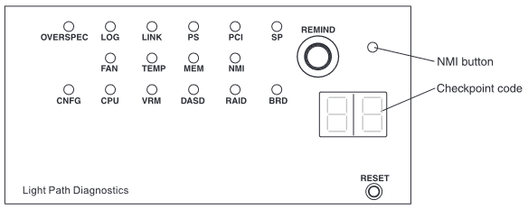
OVER SPEC: The power supplies are using more power than their maximum rating. Replace the failing power supply or remove optional devices from the HMC.
LOG: An error occurred. Check the system event log and system-error log for more information.
LOG: An error occurred. Check the system event log and system-error log for more information.
LINK: Not used on this model.
PS: Power supply 1 or 2 failed. Replace the failed power supply.
PS: Power supply 1 or 2 failed. Replace the failed power supply.
PCI: An error occurred on a PCI bus or on the system board. An additional LED is lit next to a failing PCI slot. Check the system error log for information about the error. If you cannot isolate the problem, remove one PCI adapter at a time, restarting the HMC after adapter each removal.
SP: A service processor error has been detected. Shut down the HMC normally, then remove both AC power cords for 30 seconds. Then reconnect AC power cords and boot the HMC normally. If problem continues, contact support for further assistance.
FAN: A fan failed, is operating too slowly, or was removed. A failing fan can also cause the TEMP LED to be lit. Replace the failing fan, which is indicated by a lit LED near the fan connector on the system board.
TEMP: The HMC temperature exceeded a threshold level. Ensure the room temperature is not too warm. Ensure the HMC air vents are not blocked. If a fan failed, replace the failed fan.
MEM: A memory error occurred. Replace the failing DIMM, which is indicated by the lit LED on the system board.
NMI: A machine check error occurred or the NMI button was pressed. Check the system error log for information about the error.
CNFG: A hardware configuration error occurred. If the CPU LED is lit, check the microprocessor options for compatibility. If the MEM LED is lit, check the memory DIMM options and placement for compatibility.
CPU: There is a problem with a microprocessor. Ensure the microprocessor is installed correctly and is compatible.
VRM: Not used on this model.
DASD: A hard disk drive error occurred. Check the LEDs on the hard disk drives and replace the indicated drive.
DASD: A hard disk drive error occurred. Check the LEDs on the hard disk drives and replace the indicated drive.
RAID: Not used on this model.
BRD: An error occurred on the system board. Check the LEDs on the system board to identify the component that is causing the error. Check the system error log for information about the error.
Checkpoint code display: Not used on this model.
Rear of HMC:
Power LED (green) and System-error LED (amber): These LEDs are mirrors of the LEDs with the same name from the front of the HMC.
AC LED (green): Lit solid when the power supply is receiving AC power.
DC LED (green): Flashes with the HMC is turned off. Lights solid when the HMC is turned on. If the HMC is turned on and this LED is flashing, either the power supply is not receiving valid AC power or there is a problem with the power supply or the system board.
Power-supply error LED (amber): Lights solid when there is a fault inside the power supply.
Ethernet activity LEDs: When these LEDs are lit, they indicate that the server is transmitting to or receiving signals from the Ethernet LAN that is connected to the Ethernet port.
Ethernet link LEDs: When these LEDs are lit, they indicate that there is an active link connection on the 10BASE-T, 100BASE-TX, or 1000BASE-TX interface for the Ethernet port.
7042-CR5
Front of HMC:
The optical drive activity LED flashes when the DVD drive is reading or writing a CD or DVD.
Operator information panel:
Power-on LED (green):
- Not lit: AC power is not present.
- Flashing rapidly (4 times per second): AC power is present, but the HMC is not ready to be powered on. The power-control button is disabled. This lasts approximately 1 to 3 minutes after AC power is connected.
- Flashing slowly (once per second): AC power is present, and the HMC is ready to be powered on.
- Solid: HMC is powered on.
Ethernet Activity LEDs (green): When any of these LEDs are lit, there is network activity on the indicated Ethernet port on the rear of the HMC.
System Locator LED (blue): Not used on this model.
System Information LED (amber): A noncritical event occurred with the HMC hardware. Slide the Release latch to open the Light Path Diagnostic Panel and see which LED is lit. Also, see the POST error logs in the BIOS setup menu to learn more.
System-error LED (amber): A system error occurred. Slide the Release latch to open the Light Path Diagnostic Panel and see which LED is lit.
Light path diagnostics panel:
OVER SPEC: The power supplies are using more power than their maximum rating. Replace the failing power supply or remove optional devices from the HMC.
LOG: An error occurred. Check the system event log and system-error log for more information.
LOG: An error occurred. Check the system event log and system-error log for more information.
LINK: Not used on this model.
PS: Power supply 1 or 2 failed. Replace the failed power supply.
PS: Power supply 1 or 2 failed. Replace the failed power supply.
PCI: An error occurred on a PCI bus or on the system board. An LED is also lit next to a failing PCI slot. Check the system error log for information about the error. If you cannot isolate the problem, remove one PCI adapter at a time, restarting the HMC after adapter each removal.
SP: A service processor error has been detected. Shut down the HMC normally, then remove both AC power cords for 30 seconds. Then reconnect AC power cords and boot HMC normally. If problem continues, contact support for further assistance.
FAN: A fan failed, is operating too slowly, or was removed. A failing fan can also cause the TEMP LED to be lit. Replace the failing fan, which is indicated by a lit LED near the fan connector on the system board.
TEMP: The HMC temperature exceeded a threshold level. Ensure the room temperature is not too warm. Ensure the HMC air vents are not blocked. If a fan failed, replace the failed fan.
MEM: A memory error occurred. Replace the failing DIMM, which is indicated by the lit LED on the system board.
NMI: A machine check error occurred or the NMI button was pressed. Check the system error log for information about the error.
CNFG: A hardware configuration error occurred. If the CPU LED is lot, check the microprocessor options for compatibility. If the MEM LED is lit, check the memory DIMM options and placement for compatibility.
CPU: There is a problem with a microprocessor. Ensure the microprocessor is installed correctly and is compatible.
VRM: Not used on this model.
DASD: A hard disk drive error occurred. Check the LEDs on the hard disk drives and replace the indicated drive.
DASD: A hard disk drive error occurred. Check the LEDs on the hard disk drives and replace the indicated drive.
RAID: Not used on this model.
BRD: An error occurred on the system board. Check the LEDs on the system board to identify the component that is causing the error. Check the system error log for information about the error.
RAID: Not used on this model.
BRD: An error occurred on the system board. Check the LEDs on the system board to identify the component that is causing the error. Check the system error log for information about the error.
RAID: Not used on this model.
Checkpoint code display: Not used on this model.
Rear of HMC:
Power LED (green) and System-error LED (amber): These LEDs are mirrors of the LEDs with the same name from the front of the HMC.
AC LED (green): Lit solid when the power supply is receiving AC power.
DC LED (green): Flashes with the HMC is turned off. Lights solid when the HMC is turned on. If the HMC is turned on and this LED is flashing, either the power supply is not receiving valid AC power or there is a problem with the power supply or the system board.
Power-supply error LED (amber): Lights solid when there is a fault inside the power supply.
Ethernet activity LEDs: When these LEDs are lit, they indicate that the server is transmitting to or receiving signals from the Ethernet LAN that is connected to the Ethernet port.
Ethernet link LEDs: When these LEDs are lit, they indicate that there is an active link connection on the 10BASE-T, 100BASE-TX, or 1000BASE-TX interface for the Ethernet port.
7042-CR4
Front of HMC:
The DVD drive activity LED flashes when the DVD drive is reading or writing a CD or DVD.
Operator information panel:
Power-on LED (green):
- Not lit: AC power is not present.
- Flashing: AC power is present, but the HMC is not powered on
- Solid: The HMC is powered on.
Hard drive activity LED (green): Flashes when the hard disk drive is accessing.
System Locator LED (blue): Not used on this model.
System Information LED (amber): A noncritical event occurred with the HMC hardware. Slide the Release latch to open the Light Path Diagnostic Panel and see which LED is lit. Also, see the POST error logs in the BIOS setup menu to learn more.
System-error LED (amber): A system error occurred. Slide the Release latch to open the Light Path Diagnostic Panel and see which LED is lit.
Light Path Diagnostics Panel:
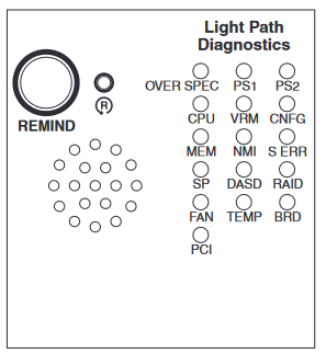
OVER SPEC: The power supplies are using more power than their maximum rating. Replace the failing power supply, or remove optional devices from the HMC.
PS1: The power supply in bay 1 failed. Replace the failed power supply.
PS2: The power supply in bay 2 failed. Replace the failed power supply.
CPU: A microprocessor failed. Ensure the microprocessor is installed correctly.
VRM: Not used on this model.
CNFG: Microprocessor configuration error. Check the microprocessor options for compatibility. Check the system error log for information indicating incompatible components.
MEM: A memory error occurred. Replace the failing DIMM, which is indicated by the lit LED on the system board.
NMI: A machine check error occurred. Check the system error log for information about the error.
S ERR: Not used on this model.
SP: The service processor failed. Shut down the HMC normally, then remove both AC power cords for 30 seconds. Then reconnect AC power cords and boot HMC normally. If problem continues, contact support for further assistance.
DASD: A hard disk drive error occurred. Check the LEDs on the hard disk drives and replace the indicated drive.
RAID: Not used on this model.
FAN: A fan failed, is operating too slowly, or was removed. A failing fan can also cause the TEMP LED to be lit. Replace the failing fan, which is indicated by a lit LED near the fan connector on the system board.
TEMP: The HMC temperature exceeded a threshold level. Determine whether a fan failed. If it has, replace it. Ensure the room temperature is not too warm. Ensure the HMC air vents are not blocked.
BRD: An error occurred on the system board. Check the LEDs on the system board to identify the component that is causing the error. Check the system error log for information about the error.
RAID: Not used on this model.
PCI: A PCI adapter or PCI riser is not correctly seated or is faulty. An LED might be lit next to the failing PCI slot inside the HMC. Check the system error log for information about the error. If you cannot isolate the problem, remove one PCI adapter at a time, restarting the HMC after adapter each removal.
PCI: A PCI adapter or PCI riser is not correctly seated or is faulty. An LED might be lit next to the failing PCI slot inside the HMC. Check the system error log for information about the error. If you cannot isolate the problem, remove one PCI adapter at a time, restarting the HMC after adapter each removal.
Rear of HMC:
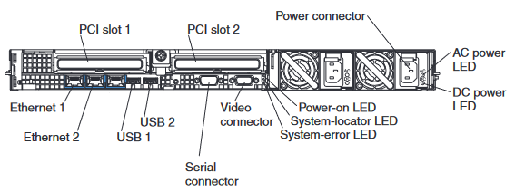
3 rear LEDs (Power-on, System-locator, System-error): These LEDs are mirrors of the LEDs with the same name from the front of the HMC.
AC LED (green): Lit solid when the power supply is receiving AC power.
DC LED (green): Flashes with the HMC is turned off. Lights solid when the HMC is turned on. If the HMC is turned on and this LED is flashing, either the power supply is not receiving valid AC power or there is a problem with the power supply or the system board.
Ethernet LEDs: There are two LEDs in corners of each Ethernet connector. The right LED lights solid when Link is present with a different color for each link speed (10Mbit, 100Mbit, 1000Mbit). The left LED flashes to indicate data is being transmitted or received.
7042-CR3
Front of HMC:
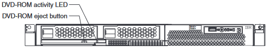
The DVD-ROM activity LED flashes when the DVD drive is reading or writing a CD or DVD.
Operator Information Panel:
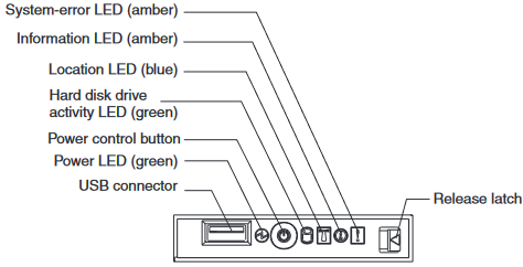
Power LED (green):
- Not lit: AC power is not present.
- Flashing: AC power is present, but the HMC is not powered on
- Solid: HMC is powered on.
Hard disk drive activity LED (green): Flashes when the hard disk drive is accessing.
Location LED (blue): Not used on this model.
Information LED (amber): A noncritical event occurred with the HMC hardware. Slide the Release latch to open the Light Path Diagnostic Panel and see which LED is lit. Also, see the POST error logs in the BIOS setup menu to learn more.
System-error LED (amber): A system error occurred. Slide the Release latch to open the Light Path Diagnostic Panel and see which LED is lit.
Light Path Diagnostics panel:
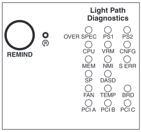
OVER SPEC: HMC is using more power than the maximum power supply rating. Remove optional hardware or replace a faulty power supply
PS1 or PS2: The indicated power supply is not installed correctly or is faulty.
CPU: System processor is not compatible or is faulty.
VRM: Ensure the processor VRM is installed correctly, or replace the faulty VRM.
CNFG: Processor or memory DIMMs are not installed in a valid configuration.
MEM: Memory DIMMs are not installed in a valid configuration.
NMI: Non-Maskable Interrupt occurred. Make sure that all HMC firmware and microcode is current. Contact support for further assistance.
S ERR: A software error occurred. Make sure that all HMC firmware and microcode is current. Contact support for further assistance.
SP: Service Processor or IMM failure. Shut down the HMC normally, then remove both AC power cords for 30 seconds. Then reconnect AC power cords and boot HMC normally. If problem continues, contact support for further assistance.
DASD: The hard disk drive might be failing.
FAN: One or more fans are not installed or operating correctly.
TEMP: The system operating temperature exceeded a threshold. Ensure the ambient temperature is within 10° to 35°C (50.0° to 95.0°F) at altitude: 0 to 914.4 m (3000 ft). (For every 1000ft above 3000ft, the maximum ambient temperature decreases by 0.75°C.) Also, make sure that all fans are operating and nothing is blocking cool airflow into the front of the HMC or warm airflow out of the back of the HMC. If the problem continues, contact support for further assistance.
BRD: Either the Time Of Day battery voltage is below 3.0 volts or a component integrated onto the system backplane failed. Check and replace the Time Of Day battery. If the problem continues, contact support for further assistance.
PCI A or PCI B or PCI C: The PCI adapter in the indicated slot is not correctly seated or is faulty.
Rear of HMC:
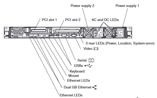
3 rear LEDs (Power, Location, System-error): These LEDs are mirrors of the LEDs with the same name from the front of the HMC.
AC LED (green): Lit solid when the power supply is receiving AC power.
DC LED (green): Flashes with the HMC is turned off. Lights solid when the HMC is turned on. If HMC is turned on and this LED is flashing, either the power supply is not receiving valid AC power or there is a problem with the power supply or the system board.
Ethernet LEDs (next to each Ethernet port): There is a pair of LEDs next to each Ethernet connector. The upper LED lights solid when Link is present. The lower LED flashes to indicate data is being transmitted or received.
Document Location
Worldwide
[{"Type":"MASTER","Line of Business":{"code":"LOB57","label":"Power"},"Business Unit":{"code":"BU058","label":"IBM Infrastructure w\/TPS"},"Product":{"code":"7063CR1","label":"Hardware Management Console (7063-CR1)"},"ARM Category":[{"code":"a8m0z000000GnS5AAK","label":"HMC"}],"ARM Case Number":"","Platform":[{"code":"PF025","label":"Platform Independent"}],"Version":"All Versions"},{"Type":"MASTER","Line of Business":{"code":"LOB57","label":"Power"},"Business Unit":{"code":"BU058","label":"IBM Infrastructure w\/TPS"},"Product":{"code":"7063CR2","label":"Hardware Management Console (7063-CR2)"},"ARM Category":[{"code":"a8m0z000000GnS5AAK","label":"HMC"}],"Platform":[{"code":"PF025","label":"Platform Independent"}],"Version":"All Versions"},{"Type":"MASTER","Line of Business":{"code":"LOB57","label":"Power"},"Business Unit":{"code":"BU058","label":"IBM Infrastructure w\/TPS"},"Product":{"code":"SSSYO2","label":"Hardware Management Console (7042-CR9)"},"ARM Category":[{"code":"a8m0z000000GnS5AAK","label":"HMC"}],"Platform":[{"code":"PF025","label":"Platform Independent"}],"Version":"All Versions"},{"Type":"MASTER","Line of Business":{"code":"LOB57","label":"Power"},"Business Unit":{"code":"BU058","label":"IBM Infrastructure w\/TPS"},"Product":{"code":"HWQQQP_165","label":"Hardware Management Console (7042-CR5)"},"ARM Category":[{"code":"a8m0z000000GnS5AAK","label":"HMC"}],"Platform":[{"code":"PF025","label":"Platform Independent"}],"Version":"All Versions"},{"Type":"MASTER","Line of Business":{"code":"LOB57","label":"Power"},"Business Unit":{"code":"BU058","label":"IBM Infrastructure w\/TPS"},"Product":{"code":"HWQQQP_173","label":"Hardware Management Console (7042-C08)"},"ARM Category":[{"code":"a8m0z000000GnS5AAK","label":"HMC"}],"Platform":[{"code":"PF025","label":"Platform Independent"}],"Version":"All Versions"}]
Was this topic helpful?
Document Information
Modified date:
06 December 2023
UID
ibm17057853