IBM Support

How to configure the cluster network of a Db2 Analytics Accelerator multi-node installation for the use of RoCE Express cards

White Papers


Abstract

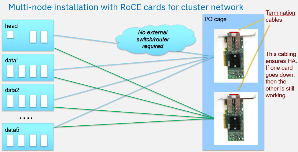
With Db2 Analytics Accelerator maintenance level 7.5.10.1 or later, the use of 'RDMA over Converged Ethernet' (RoCE) Express cards for the cluster network in Db2 Analytics Accelerator on Z multi-node installations is supported and highly recommended. The cluster network is used for inter-node communication.
RoCE Express cards provide the following benefits when compared with HiperSockets:
- RoCE cards consume significantly less CPU resources than HiperSockets; thus, more of the power of the configured IFLs is used for workload execution.
- RoCE cards increase the available CPU capacity for workload execution by ~10% compared with HiperSockets.
- RoCE cards enhance the operational system stability in high workload situations.

This document describes how to configure a cluster network based on RoCE Express cards for a Db2 Analytics Accelerator on Z multi-node installation. If the multi-node installation uses HiperSockets for the cluster network, the steps needed to migrate from the HiperSocket-based cluster network configuration to a RoCE-based cluster network configuration are described as well.

Content

For the use of RoCE Express cards in the cluster network, two bonded 25 GbE RoCE Express cards are recommended. The primary purpose of bonding is to deliver a performance increase to 50 Gb. A secondary purpose is to provide high availability.
Each RoCE Express card has two ports. Both ports must be connected by using a termination cable to ensure high availability.
As a termination cable, you can use an OM3 or OM4 50-micron multimode fiber optic cable that is terminated with an LC duplex connector.
Multiple accelerators in a single Central Electronic Complex (CEC) can share RoCE Express cards. It is sufficient to equip the system with two 25GbE RoCE Express cards and share these cards across multiple multi-node accelerators in the same CEC.
The following figure illustrates a Db2 Analytics Accelerator on Z multi-node installation that uses two RoCE cards for the cluster network. For each RoCE card, the ports are terminated by using a termination cable. Each Db2 Analytics Accelerator LPAR has access to both RoCE cards.
Multi-node installaton with RoCE cards for cluster network
Within the CEC, the RoCE cards are represented by Function IDs (FIDs), which are assigned to each port of the RoCE card during the hardware configuration. They can be obtained from the I/O Definition File (IODF), the Hardware Management Console (HMC), or the Dynamic Partition Manager (DPM) for each LPAR.
Note:  the FIDs are different for each Db2 Analytics Accelerator LPAR.
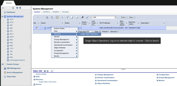
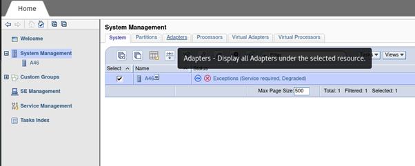
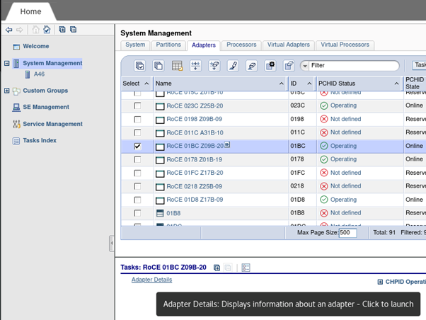
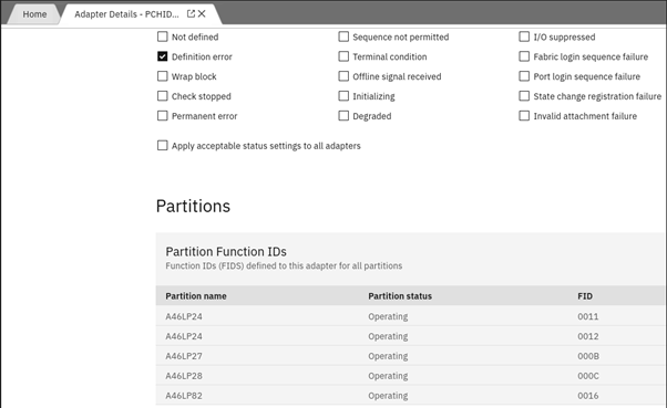
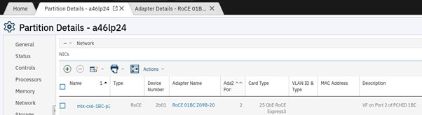
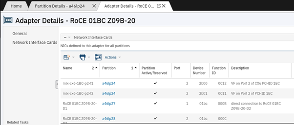
The Appendix of this document contains screen shots that show where to find the FIDs on the HMC and in the DPM.
If the multi-node Accelerator is installed on a IBM z15 or IBM z14 server, the MCL patch (P46598.532) included in bundle S85 is required to keep the FIDs after a Power On/Reset. See APAR PH59572 for more details.
Step 1: Add a RoCE card cluster network definition to the accelerator's JSON configuration file
Add a network interface definition for the RoCE cards for each accelerator LPAR (head node, data1 node, ... ) to the "runtime_environments section" of the JSON configuration file. The network interface definition consists of the following information:
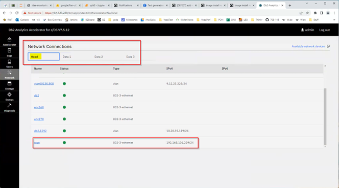
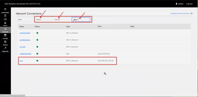
  • name: The name of the network interface definition. It must be the same for all LPARs, for example "roce".
  • ipv4: The IP address of the network interface of this LPAR. The IP address must be different for each LPAR. The IP addresses of all LPARs of a multi-node cluster must all be in the same subnet.
  • mode: The bonding mode. Use "balance-rr".
  • FID: The function ID of a RoCE card port for the LPAR. Each RoCE card has two ports, and each port has its own FID. The function IDs per RoCE card and port are different for each LPAR.
    • Note: If a defined FID contains upper-case characters, for example "000A", then provide them as lower-case characters in the JSON configuration file, for example "000a". See APAR PH57620 for more information.
The following JSON snippet shows an example of an initial configuration of a multi-node accelerator with a cluster network that uses two RoCE cards. The "network_interface_bindings" section refers to a "cluster_nw" definition named "roce". The "network_interfaces" section named "roce" contains definitions of 4 FIDs. That means that 2 RoCE cards are used that have 2 ports each. The JSON snippet shows the "roce" network interface for the "head" node only. In the complete JSON file, separate "roce" network interface sections are required for the head node and for all data nodes.
{
    "version": "7.5.11",
    "accelerator_name": "IDAAONZ",
    "accelerator_description": "Accelerator with RoCE cards",
    "accelerator_type": "multi-node",
    "db2_pairing_ipv4": "10.20.92.119/24",
    "network_interface_bindings": {
        "mgmt_nw": "activation-profile",
        "db2_nw": "db2",
        "cluster_nw": "roce"
    },
    "runtime_environments": [
        {
            "cpc_name": "A100",
            "head": {
                "lpar_name": "LP01",
                "network_interfaces": [
                    {
                        "name": "db2",
                        ...
                    },
                    {
                        "name": "roce",
                        "ipv4": "192.168.101.229/24",
                        "bond_settings": {
                            "mode": "balance-rr",
                            "slaves": [
                                {
                                   "FID": "0000"
                                },
                                {
                                   "FID": "0001"
                                },
                                {
                                   "FID": "0002"
                                },
                                {
                                   "FID": "0003"
                                }
                            ]
                        }
                    }
                ],
                ....
            },
            ....
         }
       ...
}
If a multi-node accelerator has already been set up, and you want to migrate the cluster network from HiperSockets to RoCE Express cards, proceed as follows:
  • Do not remove the HiperSockets interface definition so that the "network_interface_bindings" section initially continues to refer to the HiperSockets cluster network.
  • Add the network interface definitions for the RoCE cards to each node in the "runtime_environments" section as a currently unused network.
The following JSON snippet shows an example of this scenario. The JSON snippet shows the "roce" network interface for the "head" node only. In the complete JSON file, separate "roce" network interface sections are required for the head node and for all data nodes.
{
    "version": "7.5.11",
    "accelerator_name": "IDAAONZ",
    "accelerator_description": "Accelerator with RoCE cards",
    "accelerator_type": "multi-node",
    "db2_pairing_ipv4": "10.20.92.119/24",
    "network_interface_bindings": {
        "mgmt_nw": "activation-profile",
        "db2_nw": "db2",
        "cluster_nw": "cluster"
    },
    "runtime_environments": [
        {
            "cpc_name": "A100",
            "head": {
                "lpar_name": "LP01",
                "network_interfaces": [
                    {
                        "name": "db2",
                        ...
                    },
                    {
                        "name": "cluster",
                        "ipv4": "192.168.100.229/24",
                        "device": "0.0.0008"
                    },
                    {
                        "name": "roce",
                        "ipv4": "192.168.101.229/24",
                        "bond_settings": {
                            "mode": "balance-rr",
                            "slaves": [
                                {
                                   "FID": "0000"
                                },
                                {
                                   "FID": "0001"
                                },
                                {
                                   "FID": "0002"
                                },
                                {
                                   "FID": "0003"
                                }
                            ]
                        }
                    }
                ],
                ....
            },
            ....
         }
       ...
}
Step 2: Upload the JSON configuration file to the accelerator
For an initial multi-node accelerator deployment, use the Admin UI to provide a JSON configuration file.
When the JSON configuration file is complete, upload it by using the Admin UI.
To migrate the cluster network of an existing multi-node accelerator from HiperSockets to RoCE cards, upload and apply the updated JSON configuration file in the Admin UI. See also https://www.ibm.com/docs/en/daafz/7.5?topic=z-updating-existing-configuration.
Step 3: Verify the correct configuration of the RoCE cards
After the JSON file has been applied successfully, open the Network panel in the Admin UI and verify that for the head node and for all data nodes, a green status indicator is shown for the "roce" interfaces.  
The following sample screenshots show the green status indicator for the "roce" interfaces on the head node and the data nodes.
Roce interface availability wiht green status on head node
Roce interface availability wiht green status on data  node
Additionally, verify that the accelerator nodes can reach each other using the connections of the RoCE card cluster network:
  • In the Admin UI, open the Diagnosis panel and select the Test your network tab.
  • Starting from the head node, run ping commands to check the RoCE card cluster network IP address of each data node.
  • Continue with data1 node. Run a ping command to check the head node and the remaining data nodes by using the cluster network IP address of each node.
  • Continue with the remaining data nodes until you have pinged each node from each node on the cluster network IP address.
If one of the ping commands fails and a node cannot be reached, collect a dump; use the Dumps panel in the Admin UI to create the dump for the node that cannot be reached. Open an IBM Support case and attach the dump to the record.
Step 4: Switch to the RoCE card cluster network (only required for a migration from HiperSockets)
Having verified that the RoCE card cluster network is configured correctly, switch from the HiperSockets cluster network to the RoCE card cluster network.
  1. Edit the JSON configuration file again and change the "network_interface bindings" from "cluster_nw":"cluster" to "cluster_nw":"roce".  Note that "cluster" and "roce" are just sample names specified above in Step 2 of the JSON snippet examples. You can use different names in your JSON configuration file.
  2. Upload and apply the changed JSON configuration file using the Admin UI.
  3. Perform a Reset of the accelerator (do not select the wipe check box!) in the Admin UI to apply the new RoCE card cluster network across all accelerator nodes. This step incurs a short accelerator outage until all services have been started again. If the reset fails, perform a Shutdown on the Admin UI, followed by a re-activation of all accelerator LPARs to initiate a new restart.
  4. Optionally, you can remove the HiperSocket "network_interfaces" definition from the JSON configuration file for all nodes and upload the file again. Following the example that has been used in Step 2, the following snippet shows the HiperSocket "network_interfaces" definition to be removed from the "runtime_environments" section of all nodes.

                    {
                        "name": "cluster",
                        "ipv4": "192.168.100.229/24",
                        "device": "0.0.0008"
                    },
Summary
After all steps have been executed successfully, your multi-node accelerator uses a cluster network with RoCE Express cards for inter-node communication. That means you can now benefit from the advantages of RoCE cards, such as more IFL resources for workload execution.
Appendix
This section provides a few sample screenshots that illustrate how the FIDs can be obtained in the DPM and on the HMC.
If you use DPM, you can use the following steps:
Start from the HMC, then log on using Single Object Operations to the selectedSupport Element (SE).
image-20230913113104-1
Then display all adapters for the selected object.
image-20230913113148-2
The adapters including the RoCE cards are displayed. Select a RoCE card to display more information.
image-20230913113212-3
The FIDs of the selected RoCE card are displayed for each LPAR.
image-20230913113225-4
If you use the HMC, complete the following steps:
On the Systems Management display, select an accelerator LPAR and display the Partition Details. The RoCE cards are listed in the Network section.
image-20230913114250-1
Select a RoCE card and display the 'Adapter Details', which include the FIDs of the RoCE card for the selected LPAR. Repeat the steps for the other accelerator LPARs.
image-20230913114907-2

[{"Type":"MASTER","Line of Business":{"code":"LOB10","label":"Data and AI"},"Business Unit":{"code":"BU059","label":"IBM Software w\/o TPS"},"Product":{"code":"SS4LQ8","label":"Db2 Analytics Accelerator for z\/OS"},"ARM Category":[{"code":"a8m0z000000072oAAA","label":"Install and Migrate"}],"Platform":[{"code":"PF035","label":"z\/OS"}],"Version":"7.5.0"}]

Document Information

Modified date:
26 March 2024

UID

ibm17031391