News
Abstract
Physical System Perspectives
Content
- In Collection Services package
- Physical System folder
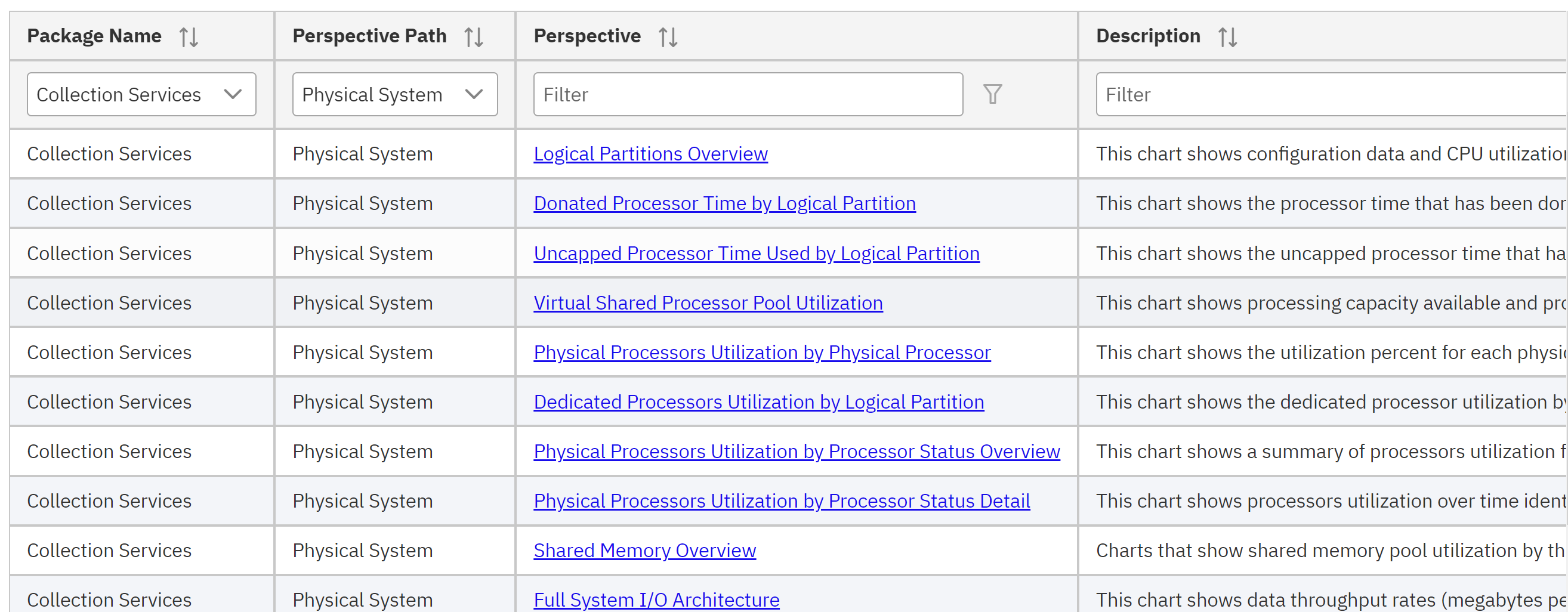
- Physical System folder

These charts all require data in the collection file QAPMBUSINT.
Attached is a presentation from a Architecture Work Group - I/O Performance which resulted in these perspectives to provide HSL & InfiniBand (12X) performance assessments: Baker - HW0624_PDI.pdf
Collection of cross partition data must be enabled through a setting in the HMC: HMC Option to Turn On Collection of Full Frame Performance Data
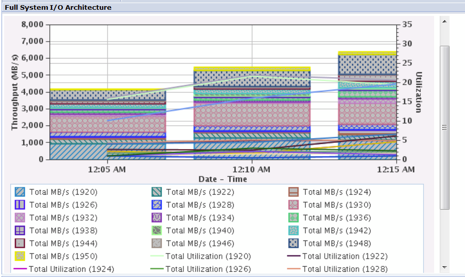
Full System I/O Architecture - This chart shows data throughput rates (megabytes per second) for selected I/O architecture components and their utilization for all the 12X loops and PCIe Gen2 enclosures over time for the selected collections. Use this chart to select a bus for viewing its detailed statistics.
Uses data from QAPMBUSINT BUTYPE = 4 (12X Loop) and 6 (I/O hub)
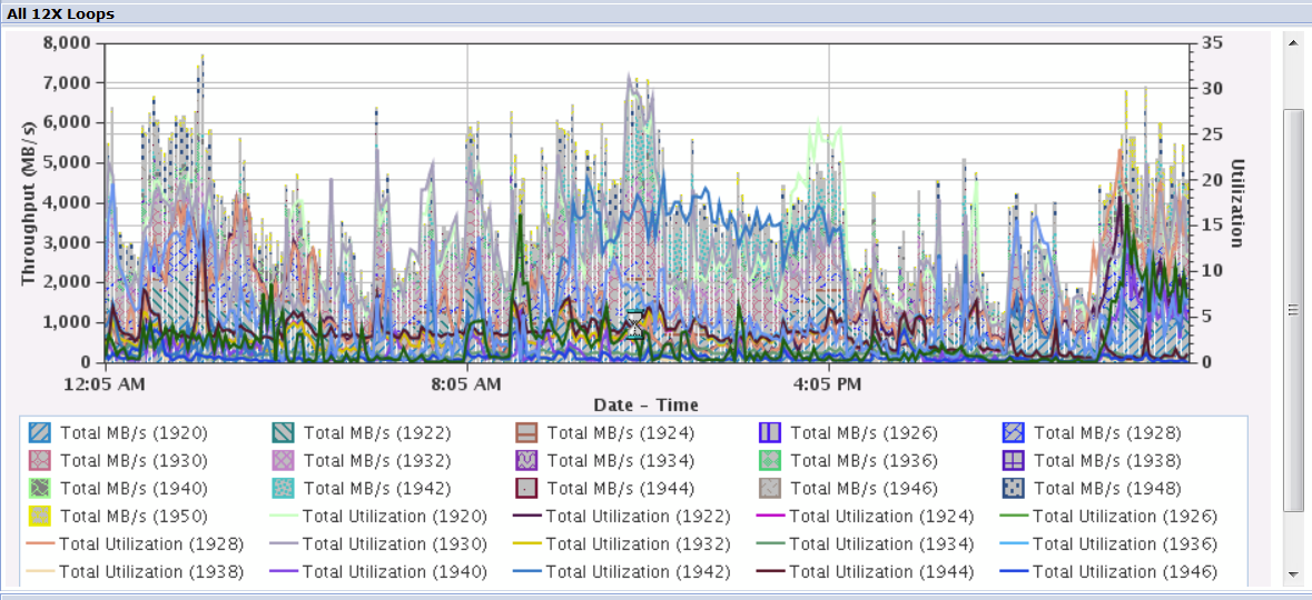
All 12X Loops - This chart shows data throughput rates (megabytes per second) for selected I/O architecture components and their utilization for all the 12X loops over time for the selected collections. Use this chart to select a bus for viewing its detailed statistics
Uses data from BUTYPE = 4 (12X Loop)
All PCIe Gen2 - This chart shows data throughput rates (megabytes per second) for selected I/O architecture components and their utilization for all PCIe Gen2 enclosures over time for the selected collections. Use this chart to select a bus for viewing its detailed statistics.
Uses data from BUTYPE = 6 (I/O hub)
If no data for the BUTYPE exists in the database collection file QAPMBUSINT, then the chart will be blank and the table data behind the chart will be empty.
QAPMBUSINT
Field Information:
| Field Name | Description | Attribute |
|---|---|---|
| INTNUM | Interval number: The nth sample database interval based on the start time specified in the Create Performance Data (CRTPFRDTA) command. | PD (5,0) |
| DTETIM | Interval date and time. The date and time of the sample interval. | C (12) |
| INTSEC | Elapsed interval seconds: The number of seconds since the last sample interval. | PD (7,0) |
| BUNBR | Bus number. The hardware assigned number associated with the bus or hub. | B (9, 0) |
|
BUTYPE
|
Bus type. Supported bus types are:
|
B (4, 0)
|
| BUDFMT | Bus data format. This field is being provided to help understand what data is instrumented by the hardware components of the bus should there be future differences. | Char (4) |
| BUATTR1 | Bus attribute 1. The meaning of this field depends on the bus type (BUTYPE) field.
|
B (4, 0) |
| BUPKTSND | Packets sent. Note: not supported for type 6 |
B (18, 0) |
| BUPKTRCV | Packets received. Note: not supported for type 6 |
B (18, 0) |
| BUBYTESND | Bytes sent. Note: not supported for type 4 |
B (18, 0) |
| BUBYTERCV | Bytes received. Note: not supported for type 4 |
B (18, 0) |
| BUMAXRATE | Maximum byte rate. The estimated maximum rate that data may be both sent and received in bytes per second. | B (18, 0) |
| BUDATA1 | The meaning of this field depends on the type (BUTYPE) field:
|
B (18, 0) |
| BUDATA2 | The meaning of this field depends on the type (BUTYPE) field:
|
B (18, 0) |
QAPMBUS
Note: only fields applicable to these perspectives are included)
Field Information:
| Field Name | Description | Attribute |
|---|---|---|
| BUKBYO | Kilobytes DMAed out | PD (11,0) |
| BUKBYI | Kilobytes DMAed in | PD (11,0) |
| BUCAT | Bus category. This field indicates if this bus record has some special characteristics, which may require a special interpretation of its performance data. Each bit in this field has an independent meaning:
|
BINCHAR(1) |
| BUHUB | Hub number. If this bus is associated with an I/O hub, this is the number of that hub. (Note: an I/O hub may be imbedded in the backplane) | B(9,0) |
| BUMAXRATE | Maximum byte rate. When available from hardware, this is the estimated maximum rate that data may be both sent and received in bytes per second through the hardware port. | B(18,0) |
| BUCBSND | Command bytes sent. When available from hardware, this is the number of command bytes sent through the hardware port. | B(18,0) |
| BUDBSND | Data bytes sent. When available from hardware, this is the number of data bytes sent through the hardware port. | B(18,0) |
| BUCBRCV | Command bytes received. When available from hardware, this is the number of command bytes received through the hardware port. | B(18,0) |
| BUDBRCV | Data bytes received. When available from hardware, this is the number of data bytes received through the hardware port. | B(18,0) |
Was this topic helpful?
Document Information
Modified date:
23 April 2023
UID
ibm11127895