Product Documentation
Abstract
Overview of input and output ports available on the xSeries 200 and 220
Content
| Port connectors |
|---|
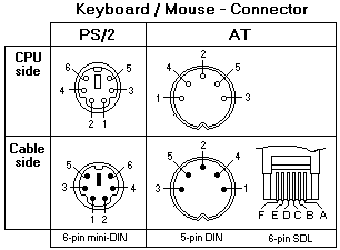
Auxiliary-device (pointing device) port

The system board has one auxiliary-device port that supports a mouse or other pointing device.
Parallel port
The server has one parallel port. This port supports three standard Institute of Electrical and Electronics Engineers (IEEE) 1284 modes of operation:
- Standard Parallel Port (SPP)
- Enhanced Parallel Port (EPP)
- Extended Capability Port (ECP).
Note: You can use the Configuration/Setup Utility program to configure the parallel port as bidirectional; that is, so that data can be both read from and written to a device. In bidirectional mode, the server supports the ECP and EPP modes.
Serial Ports
The server has two standard 9-pin male D-shell serial (communication) ports; serial port A and serial port B. Some application programs require specific ports, and some modems function properly only at certain serial port addresses. You might need to use the Configuration/Setup Utility program to change serial port address assignments to prevent or resolve address conflicts.
Viewing or changing the serial-port assignments
- Restart the server and watch the monitor screen.
- Press F1 when the message Press 1 or Configuration Setup appears.
- Select Devices and I/O Ports; from the main menu, and press Enter.
- Select the serial port; then, use the arrow keys to advance through the available settings.
- Select Save Settings; then, select Exit Setup to exit from the Configuration/Setup Utility main menu.
Ethernet port
This controller provides an interface for connecting to 10Mbps or 100Mbps networks and provides full-duplex (FDX) capability, which enables simultaneous transmission and reception of data on the Ethernet local area network (LAN).
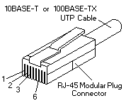
To access the Ethernet port, connect a Category 3, 4 or 5 unshielded twisted-pair (UTP) cable to the RJ-45 connector on the rear of the server.

Note: The 100BASE-TX Fast Ethernet standard requires that the cabling in the network be Category 5 or higher.
| Configuring the Ethernet controller |
|---|
When you connect the server to the network, the Ethernet controller for that Ethernet port automatically detects the data-transfer rate (10Mbps or 100Mbps) on the network and then sets the controller to operate at the appropriate rate. Further, if the Ethernet port that the server is connected to supports auto-negotiation, the Ethernet controller will set the appropriate duplex state.
The Ethernet controller is a PCI Plug and Play device. You do not need to set any jumpers or configure the controller for the operating system before you use the Ethernet controller. However, you must install a device driver to enable the operating system to address the Ethernet controllers. The device drivers are provided on the ServerGuide CDs.
Failover for redundant Ethernet
The IBM Netfinity 10/100 Ethernet Adapter or the IBM 10/100 Etherjet PCI family of adapters are optional redundant network interface cards (NIC adapter) that you can install in the server.
If you install this NIC adapter and connect it to the same logical segment as the primary Ethernet controller, you can configure the server to support a failover function. You can configure either the integrated Ethernet controller or the NIC adapter as the primary Ethernet controller. In failover mode, if the primary Ethernet controller detects a link failure, all Ethernet traffic associated with it is switched to the redundant (secondary) controller. This switching occurs without any user intervention. When the primary link is restored to an operational state, the Ethernet traffic switches back to the primary Ethernet controller.
| Universal Serial Bus (USB) ports |
|---|
The server has two Universal Serial Bus (USB) ports, which configure automatically. USB is a serial interface standard for telephony and multimedia devices. It uses Plug and Play technology to determine the type of device that is attached to the connector.
Note: If you attach a standard (non-USB) keyboard to the keyboard connector, the USB ports and devices will be disabled during the power-on self-test (POST). If you install a USB keyboard that has a mouse port, the USB keyboard emulates a mouse, and you will not be able to disable the mouse settings in the Configuration/Setup Utility program.
USB cables and hubs
You need a 4-pin cable to connect devices to USB 1 or USB 2. If you plan to attach more than two USB devices, you must use a hub to connect the devices. The hub provides multiple connectors for attaching additional external USB devices.
USB technology provides up to 12 megabits-per-second (Mbps) speed with a maximum of 127 external devices and a maximum signal distance of five meters (16 ft) per segment.
USB-port connectors
Each USB port has an external connector on the system board for attaching USB-compatible devices.
| Audio connectors |
|---|
The audio connectors are used to connect external audio equipment to the server.

Line out
This connector is used to send audio signals from the server to external devices, such as powered speakers with built-in amplifiers, headphones, multimedia keyboards, or the audio Line in connector on a stereo system.
Line in
This connector is used to accept audio signals from external devices, such as line output from a stereo, television, or musical instrument into the server sound system.
Mic
This connector is used to connect a microphone to the server when you want to record voice or other sounds on the hard disk drive. It might also be used by speech recognition software.
MIDI connector
The musical instrument digital interface (MIDI) connector allows the server to interact with musical instruments and other musical equipment. You might use the MIDI connector as an interface between the server and a synthesizer to edit and store sound information for the synthesizer on the server.
![]()
| Video port |
|---|
The server comes with an integrated super video graphics array (SVGA) video controller. This controller is not removable, but you can disable it by installing a PCI video adapter.

Note: If you install a PCI video adapter, the server BIOS will automatically disable the integrated video controller.
| Ultra 3/160 SCSI connector |
|---|
Certain xSeries 200 server models come with a SCSI adapter, which supports a single Ultra 3/160/MB SCSI channel in a full-featured PCI 2.1-/2.2-compliant bus master package. This configuration supports a zero wait state, 32-bit memory transfers at 160 Mbytes/second, when LVD SCSI peripherals are attached. This channel supports up to 15 SCSI devices.
![]()
Document Location
Worldwide
Was this topic helpful?
Document Information
Modified date:
24 January 2019
UID
ibm1MIGR-45049