Product Documentation
Abstract
Installation for the Netfinity 5600.
Content
To complete the installation, you must reinstall the cover, reconnect all the cables that you disconnected in Preparing to install options , and, for certain options, run the Configuration/Setup Utility program.
Follow the instructions in this section.
- If you have a tower model, continue with Completing the tower model installation .
- If you have a rack model, go to Completing the rack model installation below.
Completing the tower model installation
To complete the installation for the tower model:
1. Install the left-side cover, if it was removed.
2. Install the trim bezel, if it was removed.
3. Install the server door, if it was removed.
4. Restart the server.
5. Update device records and reconfigure the server (see Updating device records and reconfiguring the server ).
To install the server left-side cover:
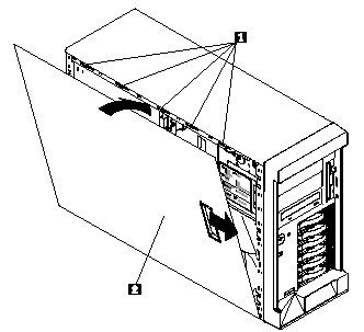
1 Slots
2 Left-side cover
a. Align the left-side cover 2 with the left side of the server, about 25 mm (1 inch) from the front of the server; place the bottom of the left-side cover on the bottom rail of the left-side side of the chassis.
b. Insert the tabs at the top of the cover into the slots 1 at the top of the server side.
c. Hold the cover against the server and slide the cover toward the front of the server until the cover clicks into place.
To install the trim bezel:
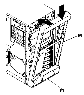
1 Trim bezel
2 Slots (hidden by bezel)
a. Place the tabs at the bottom edge of the trim bezel 1 in the slots 2 at the bottom front of the server. b. Press the top of the bezel toward the server until the bezel clicks into place.
To install the server door:
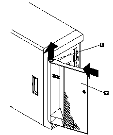
1 Flange
2 Server door
a. Set the door 2 on the bottom hinge.
b. Press the flange 1 downward while pressing the top of the door toward the server, until the flange connects with the top hinge. Release the flange.
6. Close and lock the server door.
| Attention Be sure to maintain a clearance of at least 127 mm (5 inches) on the front and rear of the server to allow for air circulation. |
7. If you disconnected any cables from the back of the server, reconnect the cables; then, plug the power cords into properly grounded electrical outlets.
| NOTE: If necessary, see Input/output connectors and expansion slots for connector locations. |
Completing the rack model installation
To complete the installation for the rack model:
1. Install the top cover, if it was removed.
2. Install the trim bezel, if it was removed.
3. Restart the server.
4. Update device records and reconfigure the server (see Updating device records and reconfiguring the server ).
To install the server top cover:
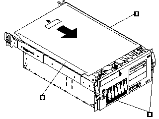
1 - Top cover
2 - Side latches
3 - Flanges
a. Align the top cover .1/ with the top of the server, about 25 mm (1 inch) from the front of the server; the flanges on the left and right sides of the cover should be on the outside of the server chassis.
b. Hold the cover against the server and slide the cover toward the front of the server until the cover clicks into place.
To install the trim bezel:
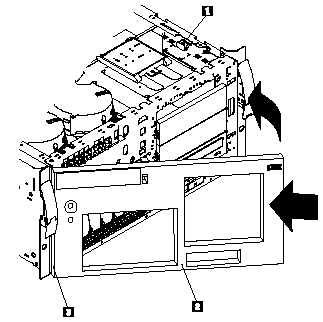
1 -Bezel-release lever
2 - Trim bezel
3 - Slots (hidden by bezel)
a. Place the tabs on the left side of the trim bezel in the slots .3/ at the left front of the server.
b. Press the right end of the bezel toward the server until the bezel clicks into place.
5 - If you disconnected any cables from the back of the server, reconnect the cables; then, plug the power
cords into properly grounded electrical outlets.
| NOTE: If necessary, see Input/output connectors and expansion slots for connector locations. |
Document Location
Worldwide
Was this topic helpful?
Document Information
Modified date:
23 January 2019
UID
ibm1MIGR-4HPTT6