Product Documentation
Abstract
This document contains Adapter card installation and removal instruction for Netfinity 5600
Content
IBM Netfinity 5600 adapter cards
You can add adapters to extend the capabilities and power of the server. Many adapters provide bus-master capabilities, which enable the adapters to perform operations without interrupting the server's microprocessor. You can install up to five peripheral component interconnect (PCI) adapters in the expansion connectors, called slots, on the system board of the server.
In three of the PCI slots, you can install a new PCI adapter or replace an existing PCI adapter with the same type of adapter without turning off the server power and restarting the system, if these features are supported by the operating system. These slots are called hot-pluggable PCI slots. They are also referred to as hot-plug PCI slots. The two remaining PCI slots support standard (non-hot-plug) PCI adapters.
The server comes with a video controller. This video controller is an integrated component on the system board. It is not in an expansion slot. The integrated video controller has super video graphics array (SVGA) technology. The integrated video controller is not removable. If you want to disable this controller and use a video adapter instead, you can install a video adapter in an expansion slot. When you install a video adapter, the server BIOS automatically disables the integrated video controller.
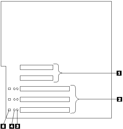
The following illustration shows the location of the PCI expansion slots on the system board:
1. Non-hot-plug 32-bit PCI slots 1 and 2 (on PCI bus A)
2. Hot-plug 64-bit PCI slots 3–5 (on PCI bus B)
3. Power LEDs for hot-swap slots
4. Internal Attention LEDs for hot-swap slots
5. External Attention LEDs for hot-swap slots
LEDs for hot-plug PCI slots: Each hot-plug PCI slot has three LEDs associated with it - two Attention LEDs and one Power LED.
- Power LED: This LED is on when the hot-plug PCI slot is active and has power. An adapter must not be added to or removed from the PCI slot when the Power LED is on. When this LED is off, the PCI slot is inactive and has no power applied. An adapter can be installed when the Power LED for the PCI slot is off. Refer to the operating system documentation to determine if it supports hot-plug PCI adapters, and, if so, how to disable the hot-plug PCI slot.
- Attention LEDs: Each hot-plug PCI slot has an Attention LED that is visible from the rear of the server and one that can be seen from inside the server. (The LEDs have the same meaning; they are duplicated to be visible from outside or inside the server.) An Attention LED flashes approximately once per second when it is on. The meaning of the Attention LEDs is defined by the operating system. Refer to the operating system documentation to determine if it supports hot-plug PCI adapters and, if so, what the Attention LEDs indicate.
The following table describes the LEDs:
| Power LED | Attention LED | Description |
|---|---|---|
| On | Flashing | The adapter requires attention. Slot still has power applied. Do not remove or install an adapter in the slot. Refer to the operating system documentation for instructions. |
| On | Off | Normal operation; no intervention is required. |
| Off | Flashing | The adapter requires intervention. Power is removed from the slot. An adapter can be removed or installed in the slot. |
| Off | Off | Power is removed from the slot. An adapter can be removed or installed in the slot. |
Before you continue with the adapter-installation procedure:
- Review the documentation that comes with the adapter and follow those instructions in addition to the instructions given in this chapter. If you need to change the switch or jumper settings on the adapter, follow the instructions that come with the adapter documentation.
- You can install full-length adapters in all expansion slots.
- You can install hot-plug PCI adapters in PCI slots 3–5, if the operating system supports this feature. Non-hot-plug PCI adapters can also be installed in these slots.
- The server supports 5.0 V and universal PCI adapters; it does not support 3.3 V adapters.
NOTE: A universal PCI adapter supports both 3.3 V and 5.0 V operation.
- The server uses a rotational interrupt technique to configure PCI adapters. Because of this technique, you can install a variety of PCI adapters that currently do not support sharing of PCI interrupts.
- PCI slots 1 and 2 are on PCI bus A and PCI slots 3–5 are on PCI bus B. Both PCI buses are primary buses. The system scans PCI slots 1 through 5 to assign system resources; then the system starts (boots) the PCI devices in the following order, if the default boot precedence has not been changed: PCI slots 1 and 2, system board SCSI devices, and then PCI slots 3 through 5. See “Start Options” in the HMM for information about changing the boot
precedence.
Note
The performance of the PCI adapters depends on the configuration of adapters in the system.
Enabling hot-plug PCI support
The Netfinity 5600 server has hot-plug PCI capability. In order to enable this feature, you must install the operating system services for hot-plug PCI support code. Click here to download the Hot-Plug PCI support code.
ATTENTION: All hot-plug operations must be done through the operating system console (or supported user interface). Failure to do this can result in a system hang or serious damage to the adapter card or system unit.
Installing a hot-plug PCI adapter
This section gives the procedure for installing a hot-plug PCI adapter. If you want to remove a hot-plug adapter, reverse the steps. If the operating system supports hot-replace PCI adapters, you can replace a failing hot-plug PCI adapter with a new adapter of the same type without turning off power to the server. If the operating system and adapter also support the hot-add feature, you can install a new adapter without turning off the power to the server.
NOTE: You do not need to turn the server off to install or remove a hot-plug PCI adapter.
Before you begin
- Read “Safety information” in the HMM.
- Read the documentation that comes with the adapter for any special requirements or restrictions.
- Read the documentation that comes with the operating system.
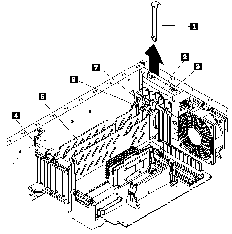
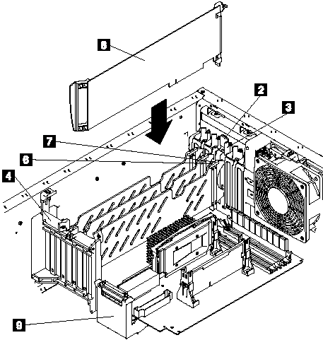
ATTENTION: Do not remove a hot-plug adapter before performing the operating-system-defined procedure for disabling the hot-plug PCI slot that contains the adapter. Failure to do so might cause the system to lock up. Refer to the operating system documentation. Refer to the following illustrations of the rack model while you perform the steps in this procedure.


1. Expansion-slot cover
2. Tab
3. Adapter retention latch
4. Adapter retention flap
5. Plastic divider
6. Power light
7. Attention light
8. Adapter
SCSI cable extender
To install a hot-plug PCI adapter
1. Remove the cover. See “Removing the left-side cover (tower model)” or “Removing the cover (rack model)” in the HMM.
2. Determine which PCI adapter expansion slot you will use for the adapter.
NOTE: Only PCI slots 3–5 can be used for hot-plug PCI adapters.
3. Disable the selected PCI slot from the operating system. (Refer to the documentation that comes with the operating system for information about disabling a hot-plug PCI slot.) Disabling the PCI slot turns off the Power light for that PCI slot.
ATTENTION: Make sure the Power light 6 for the hot-plug PCI slot is off before you continue to the next step.
4. Remove the expansion-slot cover 1:
a. Rotate the adapter retention latch 3 counterclockwise.
b. Lift the tab 2 covering the top of the expansion-slot cover 1 and then remove the expansion-slot cover from the server. Store it in a safe place for future use.
ATTENTION: Expansion-slot covers must be installed on all vacant slots. This maintains the electromagnetic emissions characteristics of the system and ensures proper cooling of system components.
5. Refer to the documentation that comes with the adapter for any cabling instructions. It might be easier for you to route any cables before you install the adapter.
6. Press on the touchpoint on the adapter retainer flap 4 at the end of the slot nearest the front of the server and rotate the adapter retainer flap upward.
7. Remove the adapter from the static-protective package.Avoid touching the components and gold-edge connectors on the adapter.
8. Place the adapter, component-side up, on a flat, static-protective surface.
9. Install the adapter 8:
a. Carefully grasp the adapter 8 by its top edge or upper corners, and align it with the expansion slot on the system board.
b. Press the adapter firmly into the expansion slot.ATTENTION: When you install an adapter in the server, be sure that it is completely and correctly seated in the system-board connector. Incomplete insertion might cause damage to the system board or the adapter.
c. Lower the tab 2 on the adapter guide over the tab on the top corner of adapter. Rotate the adapter retention latch 3 clockwise until it snaps into place.
ATTENTION: Power cannot be restored to the adapter slot if the tab is not lowered into place.
d. Close the adapter retainer flap 4.
10. Connect any needed cables to the adapter. Route cables so that the flow of air from the fans is not blocked.
11. Enable the PCI slot from the operating system. (Refer to the documentation that comes with the operating system for information about enabling a hot-plug PCI slot.) Make sure that the Power light 6 for the hot-plug PCI slot is on.
12. If you have other options to install or remove, do so now; otherwise, go to “Completing the installation”.
Installing a non-hot-plug adapter
This section gives the procedure for installing a non-hot-plug adapter. If you want to remove a non-hot-plug adapter, reverse the steps.
Before you begin
- Read “Safety information” in the HMM.
- Read the documentation that comes with the option.
Refer to the illustrations in “Installing a hot-plug PCI adapter” while you perform the steps in this procedure.
To install a non-hot-plug adapter
1. Turn off the server and peripheral devices and disconnect all external cables and power cords (see “Preparing to install options” in the HMM); then remove the cover. See “Removing the left-side cover (tower model)” or “Removing the cover (rack model)” in the HMM.
2. Determine which PCI adapter expansion slot you will use for the adapter. Check the instructions that come with the adapter for any requirements or restrictions.
3. Remove the expansion-slot cover 1:
a. Rotate the adapter retention latch 3 counterclockwise.
b. Remove the expansion-slot cover from the server. Store it in a safe place for future use. Expansion-slot covers must be installed on all vacant slots. This maintains the electromagnetic emissions characteristics of the system and ensures proper cooling of system components.
4. Refer to the documentation that comes with the adapter for any cabling instructions. It might be easier for you to route any cables before you install the adapter.
5. Press on the touchpoint on the adapter retainer flap 4 at the end of the slot nearest the front of the server and rotate the adapter retainer flap upward.
6. Remove the adapter from the static-protective package. Avoid touching the components and gold-edge connectors on the adapter.
7. Place the adapter, component-side up, on a flat, static-protective surface.
8. Set any jumpers or switches as described by the adapter manufacturer.
9. Install the adapter 8:
a. Carefully grasp the adapter 8 by its top edge or upper corners, and align it with the expansion slot on the system board.
b. Press the adapter firmly into the expansion slot. When you install an adapter in the server, be sure that it is completely and correctly seated in the system-board connector before you apply power. Incomplete insertion might cause damage to the system board or the adapter.c. Lower the tab 2 on the adapter guide over the tab on the top corner of the adapter. Rotate the adapter retention latch 3 clockwise until it snaps into place.
d. Close the adapter retainer flap 4.
10. Connect any needed cables to the adapter. Route cables so that the flow of air from the fans is not blocked.
11. If you have other options to install or remove, do so now; otherwise, go to “Completing the installation”.
Special considerations for installing a RAID adapter
You can install an optional RAID adapter in the server to control the hot-swap hard-disk drives.
To install the RAID adapter
1. Disconnect the SCSI cable from the SCSI cable extender on the system board. See the illustration in “Installing a hot-plug PCI adapter” for the location of the SCSI cable extender. (The other end of the SCSI cable is connected to the SCSI HDD backplane.) The Service Label on the inside of the cover of the server shows cable routing for an optional RAID adapter.
2. Connect the end of the SCSI cable that you disconnected from the SCSI cable extender to the RAID adapter. The other end of the cable is connected to the SCSI HDD backplane; the drives in the hot-swap bays are now connected to the RAID adapter.
3. Connect the 2-drop SCSI cable to the SCSI cable extender on the system board, and attach the device in the non-hot-swap bay to one of the drops on the other end of the 2-drop SCSI cable. The device is attached to the integrated SCSI controller.
Refer to the documentation provided with the RAID adapter for more information about installing the adapter and configuring a disk array.
Document Location
Worldwide
Was this topic helpful?
Document Information
Modified date:
23 January 2019
UID
ibm1MIGR-4N2QAM