Hardware specifications provide detailed information for your rack, including dimensions, electrical, power, temperature, environment, and service clearances.
The 5792 base rack is an optional second base frame with its own separate connection to AC power that is designed for use with model 590, and 595. A complete set of planning information is provided to address the resulting system.
The 5792 consists of multiple components, as summarized in the following table.
| Model | Description | Minimum per system | Maximum per system |
|---|---|---|---|
| FC6251 | Slimline door set for primary rack (front and rear) See Doors and covers. | 1 | 2 |
| FC6252 | Acoustic door set for primary rack (front and rear) See Doors and covers. | 1 | 2 |
| FC8691 | Optional expansion frame (16-core and 32-core only) | 0 | 1 |
| Various | Hardware Management Console (HMC)3 | 01 | 21 |
| 7040-61D (9119-590 and 9119-595), 5791 and 5794 (9406-595) | Optional I/O drawer (20 PCI cards max., 16 disk drives max.) | 0 | 122 |
| FC6200 or FC6201 | Optional integrated battery backup feature | 0 | 6 |
| Note:
|
|||
| Physical Characteristic | Slimline doors | Acoustical doors | ||
|---|---|---|---|---|
| 1 Frame | 2 Frames | 1 Frame | 2 Frames | |
| Height | 2025 mm (79.7 in.) | 2025 mm (79.7 in.) | 2025 mm (79.7 in.) | 2025 mm (79.7 in.) |
| Width | 785 mm (30.9 in.) | 1575 mm (62.0 in.) | 785 mm (30.9 in.) | 1575 mm (62.0 in.) |
| Depth | 1326 mm (52.2 in.) | 1326 mm (52.2 in.) | 1681 mm (66.2 in.) | 1681 mm (66.2 in.) |
| Weight - Maximum Configuration4 | 1264 kg (2786 lb) | 2659 kg (5863 lb) | 1273 kg (2806 lb) | 2677 kg (5901 lb) |
| Dimensions | Height | Width | Depth | Weight |
|---|---|---|---|---|
| Metric | 2311 mm | 940 mm | 1511 mm | Varies by configuration |
| English | 91 in. | 37 in. | 59.5 in. | Varies by configuration |
| Electrical characteristics | Properties | ||
|---|---|---|---|
| Rated voltage and frequency (three-phase) | 200 - 240 V ac at 50 - 60 Hz | 380 - 415 V ac at 50 - 60 Hz | 480 V ac at 50 - 60 Hz |
| Rated current, power cord with 100 A plug FC 8686 or 8687 (amperes per phase) | 60 | 32 | 24 |
| Rated current, power cord with 60 A plug, FC 8688 or 8689 (amperes per phase) | 48 | – – | – – |
| Rated current, all other power cords (amps per phase) | – – | 32 | 24 |
| Maximum power | 21.4 kW | 21.4 kW | 21.4 kW |
| Power factor, typical | 0.99 | 0.97 | 0.93 |
| Inrush current (maximum)3 | 163 A | 163 A | 163 A |
| Thermal output | 73 kBtu/hr | 73 kBtu/hr | 73 kBtu/hr |
| Dual power feature code | Standard |
| Branch circuit breaker and cord information | See Breaker rating and cord information |
| Recommended operating temperature | Nonoperating temperature (All models) | Storage temperature (All models) | Shipping temperature (All models) |
|---|---|---|---|
| 10 - 32 °C (50 - 89.6 °F) | 10 - 43 °C (50 - 109.4 °F) | 1 - 60 °C (33.8 - 140 °F) | -40 - 60 °C (-40 - 140 °F) |
| Environment | Operating | Nonoperating | Storage3 | Shipping3 |
|---|---|---|---|---|
| Maximum wet bulb | 23 °C (73.4 °F) | 27 °C (80.6 °F) | 29 °C (84.2 °F) | 29 °C (84.2 °F) |
| Noncondensing relative humidity | 8 - 80 % | 8 - 80 % | 5 - 80 % | 5 to 100 % |
| Maximum altitude3 | 3048 m (10 000 ft) | 3048 m (10 000 ft) | 3048 m (10 000 ft) | 3048 m (10 000 ft) |
| Product Configuration | LWAd (Bels) 5 | LpAM (dB)5 (bystander, 1 m) | ||
|---|---|---|---|---|
| Operating | Idle | Operating | Idle | |
| Single, typical I/O drawer in rack, nominal conditions, slimline door set | 7.5 | 7.5 | 60 | 60 |
| Single, typical I/O drawer in rack, nominal conditions, acoustical door set | 6.8 | 6.8 | 53 | 53 |
| Single, typical I/O drawer in rack plus bulk power unit, nominal conditions, slimline door set | 7.8 | 7.8 | 62 | 62 |
| Single, typical I/O drawer in rack plus bulk power unit, nominal conditions, acoustical door set | 7.1 | 7.1 | 55 | 55 |
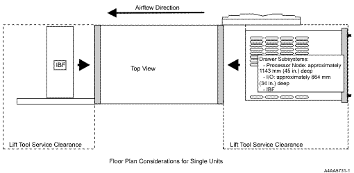
Service clearances: For a graphical representation of service clearances, see Service clearances.
Seismic considerations: See Securing the rack.
Electromagnetic compatibility compliance: This server meets the following electromagnetic compatibility specifications: FCC (CFR 47, Part 15); VCCI; CISPR-22; 89/336/EEC; BSMI (A2/NZS 3548:1995); C-Tick; ICES/NMB-003; Korean EMI/EMC (MIC Notice 2000–94, Notice 2000–72); People's Republic of China Commodity Inspection Law
Safety compliance: This server is designed and certified to meet the following safety standards: UL 60950-1; CAN/CSA C22.2 No. 60950-1; EN 60950-1; IEC 60950-1 including all national differences
Note:
|
Front-service access is necessary on the 5792 to accommodate a lift tool for the servicing of large drawers (I/O drawers). Front and rear service access is necessary to accommodate the lift tool for servicing of the optional integrated battery backup.