POWER7 information

Installing a PCI adapter contained in a cassette with the power on in the IBM i environment

You can install a PCI adapter with the power on in the IBM® i environment.

If you are installing a new feature, ensure that you have the software that is required to support the new feature and that you determine whether there are any prerequisites. To check for the prerequisites, see IBM Prerequisite website . If the required software is not installed, see the following websites to download it, and then install it before continuing:
Notes:
  • If the system is partitioned, you must determine the partition owning the I/O slot. Once the adapter is installed, the I/O slot must be powered on in the operating system.
  • If an I/O slot on a partitioned system is not owned by a partition, then the I/O slot cannot be powered on.
  • Adding an I/O slot to a partition using Dynamic Logical Partitioning (DLPAR) will power on the I/O slot as part of the DLPAR add. For information about DLPAR, see Dynamic Logical Partitioning.
  • To learn more about working in a partitioned environment, see Logical partitioning.
Important:
  • If you are removing, installing or replacing a PCI-X double-wide, quad-channel Ultra320 SCSI RAID controller, note the following concurrent maintenance information before proceeding with the instructions provided here. Concurrent maintenance of this double-wide adapter is not supported through the HMC. Concurrent maintenance must be done from within the partition operating system. In IBM i, the Hardware Service Manager (HSM) of the system or owning partition will automatically power off or on both PCI slots when either slot is selected. In AIX® or Linux, you must manually power off and on each slot separately.
    Note:
    • Both PCI slots must be powered off when installing or removing this adapter with the system power on.
    • If this adapter is the load source IOA, or any other storage IOA with critical storage devices attached to the system, this concurrent maintenance procedure should be performed by a qualified service provider.
  • Fibre Channel Adapters (5735 or 5774) installed in IBM i OS logical partitions will post errors at initial program load (IPL) if there is no device or wrap plug attached to each of the adapter's ports. Make sure that every Fibre Channel Adapter (5735 or 5774) that is installed in IBM i OS logical partition has either a wrap plug or a device attached to each of the adapter's ports. If you are exchanging a 5735 or 5774 Fibre Channel IOA, the external storage subsystem must be updated to use the worldwide port name of the new 5735 or 5774 IOA. For instructions, see Updating the worldwide port name for a new 5735 or 5774 IOA.
  • If you are replacing a 2748, 2757, 2763, 2767, 2778, 2780, 2782, 5702, 5709, or 570B storage IOA, take note of the following: Depending on the configuration of the system, the storage IOA cache might have been disabled to allow the attachment of OEM storage that emulates a load source drive. If you are replacing a storage IOA that has its cache disabled, configure the replacement IOA the same way as the IOA that you removed. If you remove hardware from the replacement IOA, return that hardware with the failed IOA.

If you do not have an HMC, complete the following steps to install a PCI adapter with the system power on in the IBM i environment:

  1. Complete the prerequisite tasks that are described in Before you begin.
  2. Take appropriate precautions for avoiding electric shock and handling static-sensitive devices. For information, see Avoiding electric shock and Handling static-sensitive devices.
  3. To determine in which slot to place the PCI adapter, refer to PCI adapter placement for information regarding slot restrictions for the adapters that can be used in this system.
  4. Access the concurrent maintenance procedures using the IBM i Hardware service manager (HSM) tools:
    1. Type strsst on the command line of the Main Menu and press Enter.
    2. Type your service tools user ID and service tools password on the System Service Tools (SST) Sign On display. Press Enter.
    3. Select Start a service tool from the System Service Tools (SST) display. Press Enter.
    4. Select Hardware service manager from the Start a Service Tool display and press Enter.
    5. Select Packaging hardware resources (system, frames, cards) from the Hardware Service Manager display. Press Enter.
    6. Select option 9 (Hardware contained within package) in the System Unit or Expansion Unit field of the unit where you are removing the card, and then press Enter.
    7. Select function F7 (Include empty positions and not owned positions) on the unit where you are removing the card.
    8. Select Concurrent Maintenance on the card position where you want to remove the card and then press Enter.
    9. Select Toggle LED blink off/on. A light-emitting diode (LED) blinks identifying the position you chose. Physically verify that this is the slot where you want to remove the adapter.
    10. Select Toggle LED blink off/on to stop the blinking LED.
    11. Select function F9 (Power off domain), and when complete then ensure that the PCI-e card slot power LED is not lit.
  5. Locate the PCI adapter slot and cassette you want to use.
  6. If the cassette you want to use does not contain a PCI adapter, continue to the next step. If the cassette you want to use does contain an active PCI adapter, see Removing a PCI adapter contained in a cassette from the system with the power on in the IBM i environment.
  7. Attach the wrist strap.
    Attention:
    • Attach a wrist strap to an unpainted metal surface of your hardware to prevent electrostatic discharge (ESD) from damaging your hardware.
    • When using a wrist strap, follow all electrical safety procedures. A wrist strap is for static control. It does not increase or decrease your risk of receiving electric shock when using or working on electrical equipment.
    • If you do not have a wrist strap, just before removing the product from ESD packaging and installing or replacing hardware, touch an unpainted metal surface of the system for a minimum of 5 seconds.
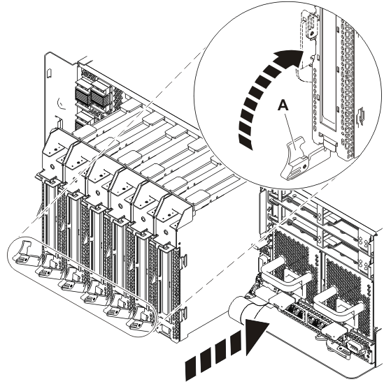
  8. Remove the cassette. Press downward on the lower cassette handle (A) as shown in the following figure. Pull the PCI cassette out of the system.
    Figure 1. Removing the PCI adapter cassette from the system
    Removing the PCI adapter cassette from the system.
  9. Install the adapter into the PCI adapter cassette, see PCI adapter single-width, fourth generation cassette.
  10. Ensure the lower cassette handle is slightly angled up toward the retainer clip, as shown in the following figure. This places the adapter in the correct position to be docked in the system.
  11. Slide the cassette into the cassette slot as shown in the following figure.
    Attention: Ensure proper alignment when you insert a PCI adapter cassette into the system.
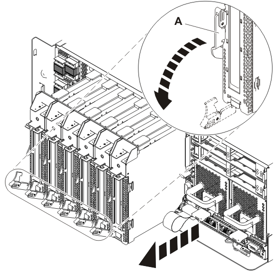
  12. When the cassette is fully inserted into the system, firmly press cassette handle (A) to lock the adapter in its connector.
    Figure 2. Installing the PCI adapter cassette in the system
    Installing the PCI adapter cassette in the system.
  13. Attach any cables that should be attached the adapter.
  14. Select Power on domain on the Hardware Resource Concurrent Maintenance display and press Enter.
  15. Select Assign to on the resource that has an asterisk (*) on the Work with Controlling Resource display. Press Enter.
  16. Wait for the Hardware Resource Concurrent Maintenance display to appear with this message:
    Power on complete
  17. Verify the installed part.
    • If you replaced the part because of a service action, verify the installed part. For instructions, see Verifying a repair.
    • If you installed the part for any other reason, verify the installed part. For instructions, see Verifying the installed part.


Send feedback Rate this page

Last updated: Thu, January 10, 2019