POWER7 information

Installing a PCI RAID and SSD SAS adapter in the 8233-E8B server, with the power on in the IBM i environment

You can install a PCI RAID and SSD SAS adapter with the system power on in the IBM® i environment.

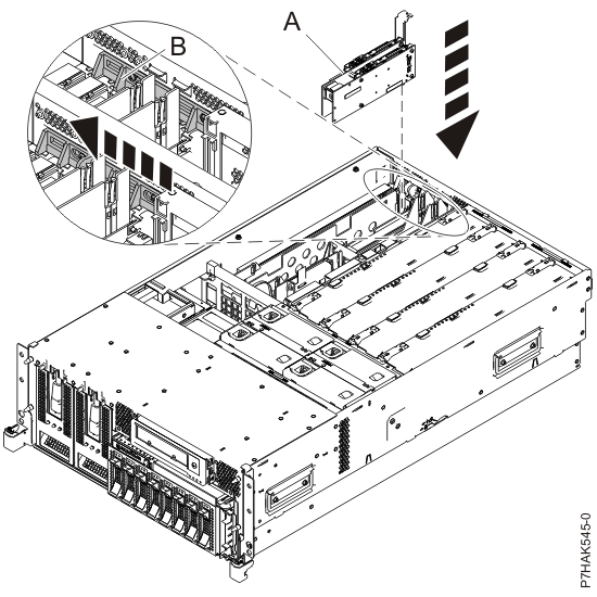
The PCIe RAID and SSD SAS adapter is a double-wide adapter. Although it plugs into a single PCIe slot, two adjacent PCIe slots are required for installation (slot 3 for plugging, slot 2 for expansion).

If you are installing a new feature, ensure that you have the software that is required to support the new feature and that you determine whether there are any prerequisites. To check for the prerequisites, see IBM Prerequisite website . If the required software is not installed, see the following websites to download it, and then install it before continuing:

If your system is managed by an HMC, use the HMC to complete the steps for installing the part in the system. For instructions, see Installing a part by using the HMC.

If you do not have an HMC, complete the following steps to install a PCIe RAID and SSD SAS with the system power on in the IBM i environment:

  1. Complete the prerequisite tasks that are described in Before you begin.
  2. Take appropriate precautions for avoiding electric shock and handling static-sensitive devices. For information, see Avoiding electric shock and Handling static-sensitive devices.
  3. If you are installing, removing, or replacing a PCI adapter in a rack-mounted system, follow these steps to remove the service access cover.
    1. Open the front rack door.
    2. Place the system unit in the service position.
    3. Remove or open the service access cover.
  4. If necessary, remove the adapter expansion slot shield.
  5. If necessary, remove the adapter from the antistatic package.
    Attention: Avoid touching the components and gold connectors on the adapter.
  6. Place the PCIe adapter, component-side up, on a flat, antistatic surface.
  7. Some PCIe adapters are shipped from the manufacturer with a blue handle or support bracket along the back edge of the card. To use adapters of this type in this system, you must remove the blue handle or support bracket from the card.
  8. Remove the PCI adapter divider if one is present. See Removing a PCI adapter divider from the 8233-E8B and 8236-E8C server.
  9. Access the concurrent maintenance procedures using the IBM i Hardware service manager (HSM) tools:
    1. Type strsst on the command line of the Main Menu and press Enter.
    2. Type your service tools user ID and service tools password on the System Service Tools (SST) Sign On display. Press Enter.
    3. Select Start a service tool from the System Service Tools (SST) display. Press Enter.
    4. Select Hardware service manager from the Start a Service Tool display and press Enter.
    5. Select Packaging hardware resources (system, frames, cards) from the Hardware Service Manager display. Press Enter.
    6. Select option 9 (Hardware contained within package) in the System Unit or Expansion Unit field of the unit where you are removing the card, and then press Enter.
    7. Select function F7 (Include empty positions and not owned positions) on the unit where you are removing the card.
    8. Select Concurrent Maintenance on the card position where you want to remove the card and then press Enter.
    9. Select Toggle LED blink off/on. A light-emitting diode (LED) blinks identifying the position you chose. Physically verify that this is the slot where you want to remove the adapter.
    10. Select Toggle LED blink off/on to stop the blinking LED.
    11. Select function F9 (Power off domain), and when complete then ensure that the PCI-e card slot power LED is not lit.
  10. Slide the adapter latch (A) into the open position, as shown in the following figure.
    Figure 1. PCI adapter or filler plate removed from the rack-mounted system unit
    Adapter or filler plate removed from the system unit.
  11. Ensure that the slot is empty. Remove the adapter filler plate if one is present.
  12. Remove the solid expansion slot cover and install the perforated expansion slot cover that shipped with your PCIe adapter. Press the expansion slot cover firmly into position in the adjacent slot to the left of the adapter slot.
  13. Carefully grasp the PCIe adapter by its top edge, and align the adapter with the expansion slot and its connector on the system backplane.
  14. Press the adapter firmly into its connector.
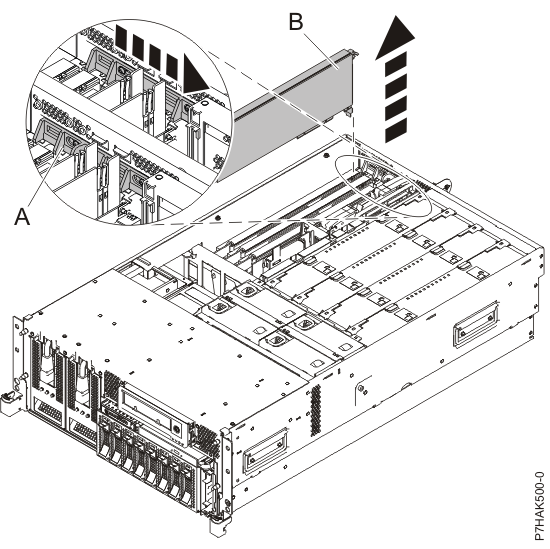
  15. Slide the adapter latch (B) back into place as shown in the following figure.
    Figure 2. PCI RAID and SSD SAS adapter replaced in the rack-mounted system unit
    Adapter or filler plate replaced in the system unit.
  16. From the Hardware Resource Concurrent Maintenance display, complete the following steps:
    1. Select Power on domain and press Enter.
    2. Select Assign to on the resource that has an asterisk (*) on the Work with Controlling Resource display. Press Enter.
    3. Wait for the Hardware Resource Concurrent Maintenance display to appear with this message:
      Power on complete
  17. Replace or close the service access cover and, if applicable, return the system to the operating position.
  18. Verify the installed part.
    • If you replaced the part because of a service action, verify the installed part. For instructions, see Verifying a repair.
    • If you installed the part for any other reason, verify the installed part. For instructions, see Verifying the installed part.


Send feedback Rate this page

Last updated: Thu, January 10, 2019