Attaching the Ethernet cables
Attach the Ethernet cables to the control enclosures and file modules.
About this task
This task guides you through connecting both the internal and external Ethernet connections for your system.
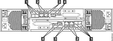
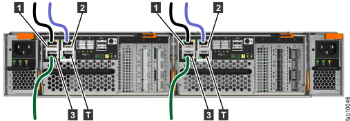
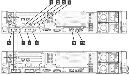
This task assumes that your initial planning has determined where the Ethernet cables are to be located. The Storwize® V7000 Unified control enclosure requires at least one and a maximum of two 1 Gbps Ethernet connections to each node canister. Refer to Figure 1, Figure 2, and Figure 3; also Table 1 and Table 2. For the file modules, the first two 1 Gbps Ethernet ports that are labeled 1 and 2 in Figure 5 are used for internal communications between the file modules.

- 1 Fibre Channel ports (8 Gbps). Each node canister has four Fibre Channel ports. They are in a block of four in two rows of two connectors. The ports are numbered 1 - 4 from left to right, top to bottom. Two ports connect to the file modules and two are connected to the SAN.
- 2 USB ports. Each node canister has two USB ports. The ports are side by side on the canister and are numbered 1 on the left and 2 on the right. One port is used during installation.
- 3 Ethernet ports (1 Gbps). Each canister has two Ethernet ports. The ports are side by side on the canister. They are numbered 1 on the left and 2 on the right on the upper canister. The port locations are inverted for the lower canister. Port 1 must be connected first; the use of port 2 is optional.
- 4 Serial-attached SCSI (SAS) ports (6 Gbps). Each node canister has two SAS ports. The ports are side by side on the canister. They are numbered 1 on the left and 2 on the right. Port 1 must be connected first if you are adding one expansion enclosure. Port 2 must be connected if you are adding a second expansion enclosure.


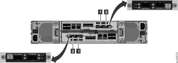
- 1 10 Gbps Ethernet port 3, which is the left port.
- 2 10 Gbps Ethernet port 4, which is the right port.
| Item | Port | Purpose | IP address is assigned by InitTool | Use |
|---|---|---|---|---|
| 3 (left port, Figure 1) | Built-in Ethernet port 1 | 1 Gbps external network connection | Yes | Management and service port for each canister, optional iSCSI. (The Storwize V7000 control enclosure must be able to communicate over the network with the file modules.) |
| 3 (right port Figure 1) | Built-in Ethernet port 2 | 1 Gbps external network connection | No | Optional management and service port, optional iSCSI |
| 1 (Figure 3) | Ethernet port 3 on a 2076-312 or 2076-324 | 10 GbE external network connection | No | Optional iSCSI |
| 2 (Figure 3) | Ethernet port 4 on a 2076-312 or 2076-324 | 10 GbE external network connection | No | Optional iSCSI |
If optional 4-port 10 Gbps Ethernet interface adapters are installed in the node canisters, connect each port to the network that will provide connectivity to that port. Connect both node canisters in a control enclosure to the same networks to provide redundant connectivity.

| Item | Port | Purpose | IP address is assigned by InitTool | Use |
|---|---|---|---|---|
| 1 (Figure 4) | Built-in Ethernet port 1 | 1 Gbps external network connection | Yes | Management and service port for each canister; optional iSCSI. (The Storwize V7000 control enclosure must be able to communicate over the network with the file modules.) |
| 2 (Figure 4) | Built-in Ethernet port 2 | 1 Gbps external network connection | No | Optional management and service port; optional iSCSI |
| 3 (Figure 4) | Built-in Ethernet port 3 | 1 Gbps external network connection | No | Optional management and service port; optional iSCSI |
| 4 (Figure 4) | Ethernet port 4 | 10 GbE external network connection | No | Optional iSCSI |
| 5 (Figure 4) | Ethernet port 5 | 10 GbE external network connection | No | Optional iSCSI |
| 6 (Figure 4) | Ethernet port 6 | 10 GbE external network connection | No | Optional iSCSI |
| 7 (Figure 4) | Ethernet port 7 | 10 GbE external network connection | No | Optional iSCSI |

| Item | Port | IP address is assigned by InitTool | Use |
|---|---|---|---|
| 1 | Ethernet port 7 | Connect to a switch for public file access | |
| 2 | Ethernet port 8 | Connect to a switch for public file access | |
| 3 | Ethernet port 9 | Connect to a switch for public file access | |
| 4 | Ethernet port 10 | Connect to a switch for public file access | |
| 5 | Ethernet port 1 | From the internal IP address range | Connect to the other file module |
| 6 | Ethernet port 2 | From the internal IP address range | Connect to the other file module |
| 7 | Ethernet port 3 | File module service and system management IP address | Connect to a switch for public file access and system management |
| 8 | Ethernet port 4 | Connect to a switch for public file access | |
| 9 | Ethernet port 5 (10 Gbps optical ) | Connect to a switch for public file access and optional system management | |
| 10 | Ethernet port 6 (10 Gbps optical ) | Connect to a switch for public file access |
If you encounter that situation, change the service IP addresses on the new nodes before connecting the Ethernet cables.
- Connect an Ethernet cable from Ethernet port 1 on the first file module to
the first Ethernet port 1 the second file module.
Refer to Figure 5 for
port locations.Note: Ethernet cables for the internal network are provided by IBM with the file modules.
- Connect an Ethernet cable from Ethernet port 2 on first file module to Ethernet port 2 on the second file module.
- Route the Ethernet cables through the cable management arms, and secure any excess using the cable retention features of the rack.
- Connect an Ethernet cable from Ethernet port 3 on the first file module to an Ethernet network. If using two Ethernet cables (as recommended), connect another Ethernet network cable to Ethernet port 4. When using only one Ethernet port, the network status is marked as degraded and an associated warning event is listed in the health center.
- Optionally, connect as many other file module Ethernet ports to network switches as you require
- Repeat the previous step for the second file module.
- Route the Ethernet cables through the cable management arm, and secure any excess using the cable retention features of the rack.
You have two 10 Gbps Fibre Ethernet ports available for host connections from each file module. Connect your network cables to the Ethernet ports in these slots as applicable. Refer to Figure 5.