Replacing the system backplane in the 9040-MR9
To replace the system backplane, complete the steps in this procedure.
Procedure
- Ensure that you have the electrostatic discharge (ESD) wrist strap on and that the ESD clip is plugged into a ground jack or connected to an unpainted metal surface. If not, do so now.
- Install the new system backplane.
- Open the packaging for the new system backplane and place it on an appropriate ESD surface.
-
Grasp the new system backplane by the front (A) or middle
(B) metal bulkheads and the rear metal bulkhead (C).
As you lower the backplane straight down into the chassis, take care to ensure that the pins on the
bottom of the backplane align with the holes in the chassis.
Figure 1. Lowering the system backplane into the chassis 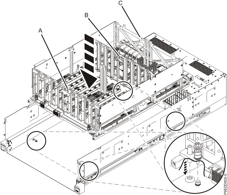
-
Using a 4 mm Hex driver, tighten the four captive screws (A) that mount
the backplane to the chassis. Refer to the following image for the location of the screws.
Figure 2. System backplane screw locations 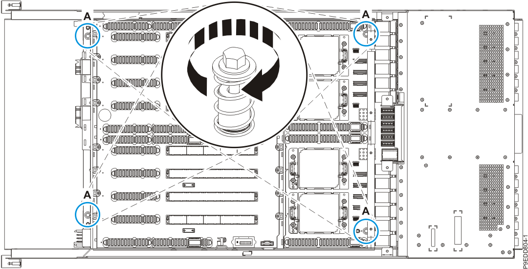
- Replace the power midplane.
- Grasp the power midplane by its bulkhead (A) and lower it into
the system chassis. Refer to the following image.
Figure 3. Replacing the power midplane 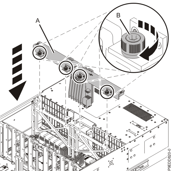
- Using a 4mm Hex driver, tighten the four captive thumbscrews (B) on the power midplane bulkhead. Refer to the previous image.
- Using a 4mm Hex driver, tighten the four captive screws (C) so
that the power midplane bulkhead is securely attached to the system chassis. Refer to the following
image.
Figure 4. Tightening the captive screws on the power midplane bulkhead 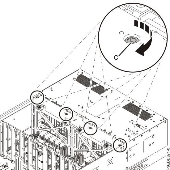
- Reconnect the cable to its connector on the power midplane.
Figure 5. Reconnecting the cable to its connector on the power midplane 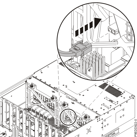
- Grasp the power midplane by its bulkhead (A) and lower it into
the system chassis. Refer to the following image.
-
Remove the socket dust covers from the system processor module sockets on the new system
backplane.
- Grasp the latches on both sides of the socket dust cover and squeeze them inwards until the latches release from the pins on the system backplane.
-
Lift the socket dust cover straight up as shown in the following figure. Set the dust cover
aside.
Figure 6. Removing the socket dust covers 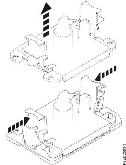
- Repeat steps 4.a through 4.b to remove the other socket dust covers.
-
Install the system processor modules from the original system backplane in the new system
backplane.
Tip: As you replace parts inside the system, refer to your notes about the location for each part. It is important that you replace parts in the exact location from which they were removed.
-
Ensure that the removal tool is in the open position as shown in the following image. The
middle ring must be pushed down and blue tabs must be turned inward.
Figure 7. Ensuring that the removal tool is in the open position 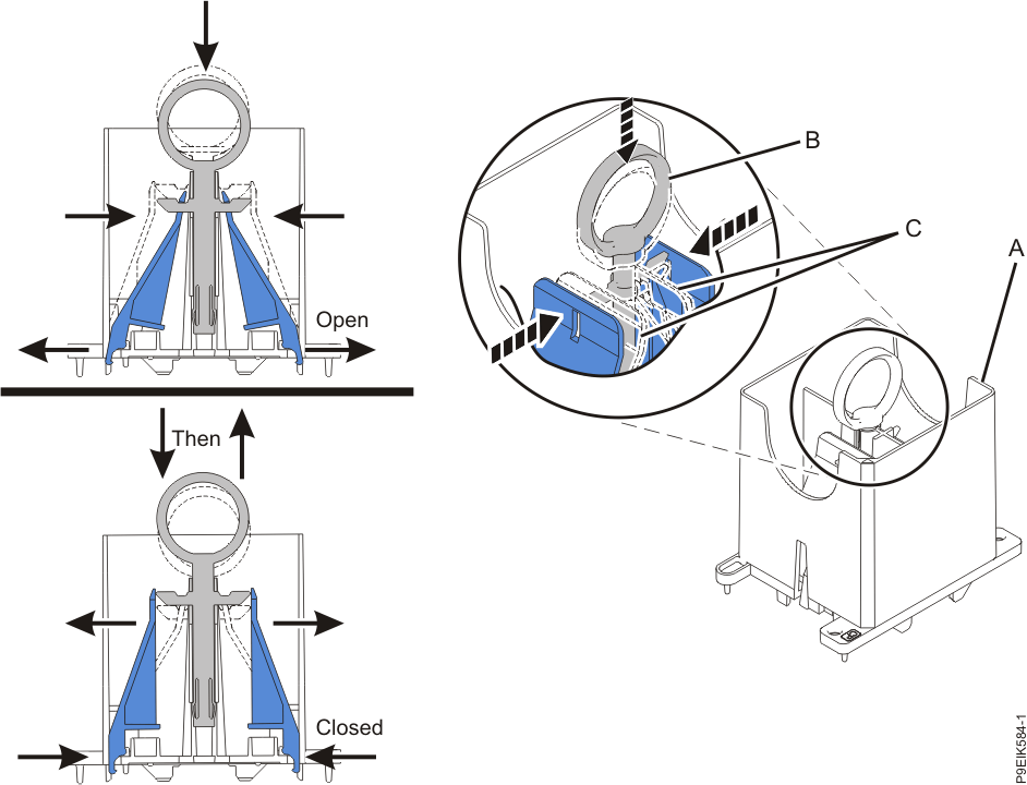
-
Lower the tool over the system processor module as shown in the following image. Ensure that
the beveled edge on the tool aligns with the beveled edge of the processor. Ensure that the two
guide pins (A) are inserted into the alignment holes
(B) on each side of the tool.
Figure 8. Lowering the removal tool onto the system processor module 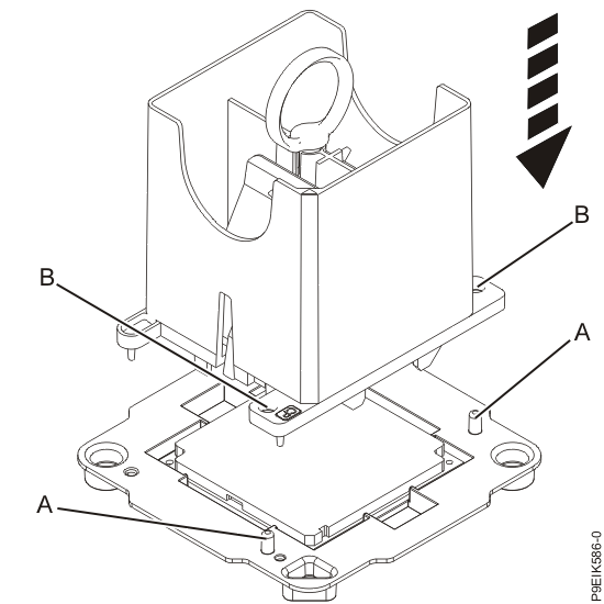
-
With the removal tool sitting on top of the system processor module, push down on the ring
(A) slightly so that the blue tabs (B) snap outward
and the jaws engage with the system processor module (C) as shown in the
following figure.
Make sure that both of the tool jaws are locked onto the system processor module by pushing down on the tool.Important: Do not press the blue release tabs until directed to do so later.
Figure 9. Locking the system processor module into the tool 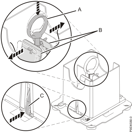
- Hold the sides of the tool with system processor module and carefully lift the tool out of the system processor module tray.
-
Lower the tool and system processor module onto the socket. Align the beveled corner of the
tool with the beveled corner on the socket. Align the guide pins (A) with the
alignment holes (B) on each side of the tool. Use care to lower the tool
evenly without tilting the tool.
Refer to the following figure.Note: Do not attempt to slide the tool and the system processor module in any direction while the system processor module is touching the socket. If the tool and the system processor module are not aligned with the guide pins, lift the tool and the system processor module and reposition them.
Figure 10. Installing the system processor module 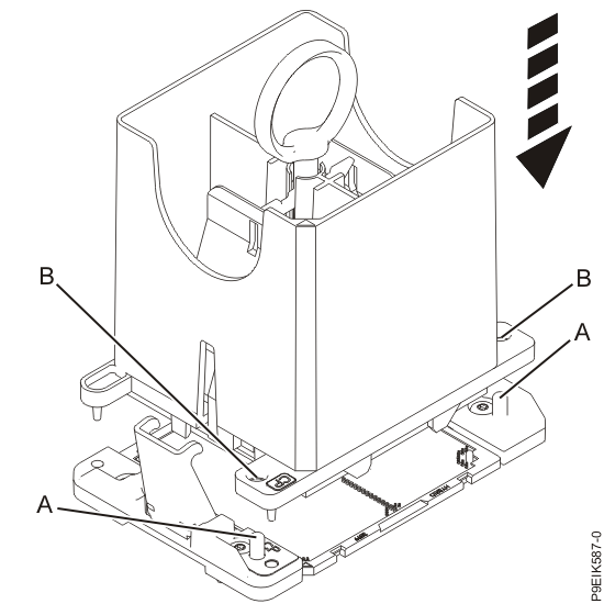
-
Open the latches that hold the system processor module in the supplied removal tool
(A) as shown in the following figure. Push down on the ring
(B) while pressing in on the tabs (C).
Figure 11. Removing the system processor module tool 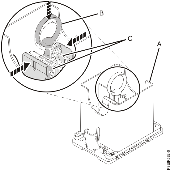
- Lift the tool off the system processor module.
- Repeat steps 5.a through 5.g for all of the system processor modules.
-
Ensure that the removal tool is in the open position as shown in the following image. The
middle ring must be pushed down and blue tabs must be turned inward.
- Install new thermal interface material (TIM) and the new
heat sinks in the new system backplane.
- Open the TIM packaging and carefully remove the TIM, holding it by the edges of the carrier strip and holding it away from the shipping container.
-
Remove the protective film from the clear carrier strip by using the supplied tweezers.
Note: The TIM must remain flat. Small wrinkles are acceptable, but folds are not acceptable.
-
Using the tweezers, remove the TIM from the carrier strip and center it onto the system
processor module.
The silver-colored TIM must have the red stripe up. Align the beveled corners of the silver-colored TIM and the system processor module (A), as shown in the following figure.
Use the alignment marks on the top of the system processor module to properly place the TIM. You must center the TIM in the alignment marks on the system processor module.
Figure 12. Installing the silver-colored TIM onto the processor. The red stripe must be up. 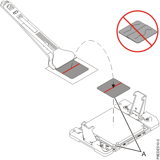
-
Place the heat sink on the TIM as shown in the following figure.
Figure 13. Placing the heat sink on the TIM 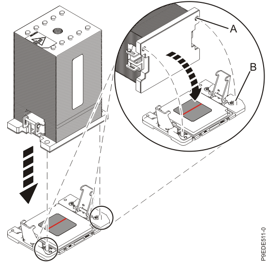
- Ensure that the heat sink load arms are engaged as shown by (A) in the following figure.
-
Tighten the center load screw clockwise by using the supplied hex key as shown by
(B) in the following figure until a firm stop is reached. If the heat sink
moves noticeably, the load arms are not engaged. Unscrew the center load screw and repeat this step
again.
Figure 14. Tightening the center load screw on the heat sink 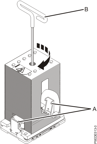
- Repeat steps 6.a through 6.f to install new TIM and the new heat sinks on the remaining system processor modules.
- Install the socket dust covers on the
original system backplane. The socket dust covers protect the sockets during shipping.
- Lower the socket dust cover over
one of the sockets on the system backplane and ensure that the holes (B) on
the socket dust cover align with the two guide pins (A) on the system
backplane. Push straight down until the latches (D) on the socket dust cover
engage with the latches (C) on the backplane. Refer to the following
figure.
Figure 15. Placing the dust covers on the system processor module sockets on the system backplane 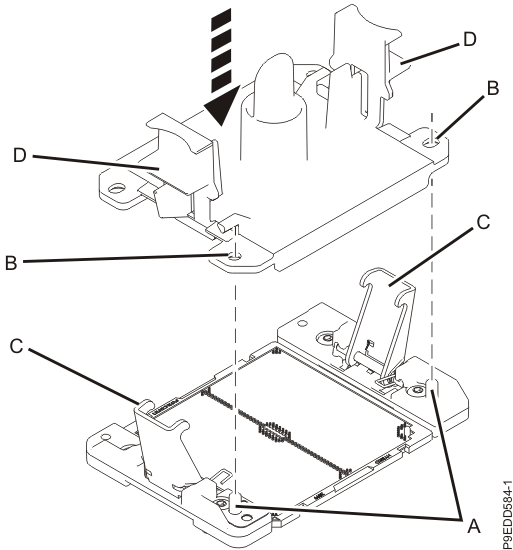
- Repeat step 7.a to install socket dust covers on the remaining system processor module sockets.
- Lower the socket dust cover over
one of the sockets on the system backplane and ensure that the holes (B) on
the socket dust cover align with the two guide pins (A) on the system
backplane. Push straight down until the latches (D) on the socket dust cover
engage with the latches (C) on the backplane. Refer to the following
figure.
- Replace the processor voltage regulator
modules or processor voltage regulator module fillers in locations
P1-C13, P1-C16, P1-C17, and P1-C20.
- With the levers (A) in the open position, hold the voltage regulator module or filler by its levers and lower the voltage regulator module or filler into its slot in the system. Refer to the following image.
- Gently push the voltage regulator module or filler into its connector.
- Rotate the levers in the direction that is shown and press down on the latches to secure the voltage regulator module or filler in its slot.
- Repeat steps 8.a through 8.c to replace the remaining processor voltage regulator modules or fillers.
Figure 16. Replacing the processor voltage regulator modules or fillers 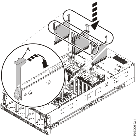
- Replace the vital product data (VPD) card in location
P1-C24.
- Align the VPD card in its slot on the system backplane. Refer to the following image.
- Press the VPD card firmly into place until it is fully seated.
Figure 17. Replacing the VPD card 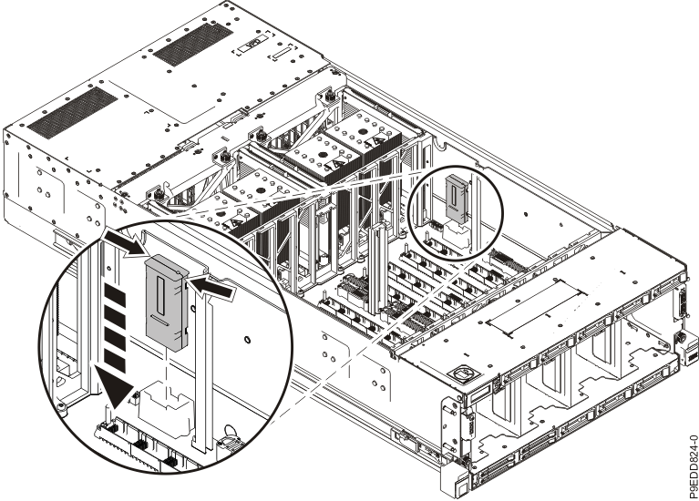
- Reconnect the rear USB cable (A)
in the USB socket on the system backplane as shown in the following figure.
Figure 18. Reconnecting the rear USB cable in the USB socket on the system backplane 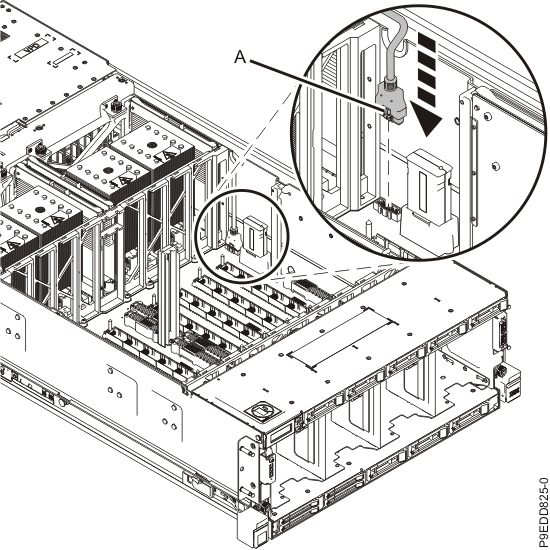
- Replace the I/O voltage regulator module in location
P1-C23.
- With the levers (A) in the open position, hold the voltage regulator module by its levers and lower the voltage regulator module into its slot in the system. Refer to the following image.
- Gently push the voltage regulator module into its connector.
- Rotate the levers in the direction shown and press down on the latches to secure the voltage regulator module in its slot.
Figure 19. Replacing the I/O voltage regulator module 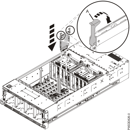
- Replace the standby voltage regulator module in
location P1-C22.
- With the levers (A) in the open position, hold the voltage regulator module by its levers and lower the voltage regulator module into its slot in the system. Refer to the following image.
- Gently push the voltage regulator module into its connector.
- Rotate the levers in the direction shown and press down on the latches to secure the voltage regulator module in its slot.
Figure 20. Replacing a standby voltage regulator module 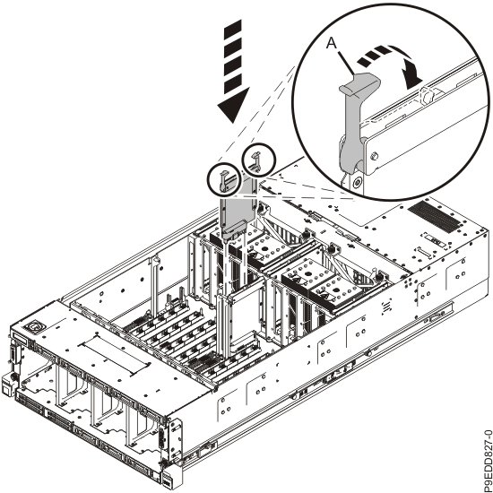
- Replace the trusted platform module (TPM) card in location
P1-C21.
- Insert the TPM card into its slot on the system backplane. Refer to the following image.
- Push the TPM card into place until it is fully seated.
Figure 21. Replacing the TPM card 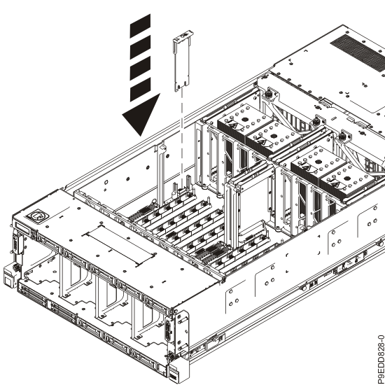
- Replace the memory module riser cards in locations
P1-C26, P1-C27, P1-C28, P1-C29, P1-C32, P1-C33, P1-C34, and P1-C35.
- Ensure the release latches (A) are fully open to a 90 degree angle as shown in the following figure.
- Align the memory module riser card with the connector.
- Press the memory module riser card firmly into the connector.
- Rotate the release latches into the closed position, and press the release latches down to ensure that the memory module riser card is fully seated into the connector.
- Repeat steps 14.a through 14.d for the remaining memory module riser cards.
Figure 22. Replacing the memory module riser cards 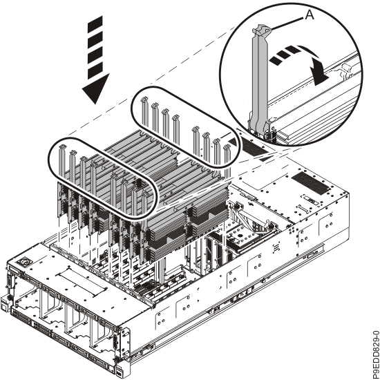
- Replace the memory voltage regulator modules in
locations P1-C25, P1-C30, P1-C31, and P1-C36.
- With the levers (A) in the open position, hold the voltage regulator module by its levers and lower the voltage regulator module into its slot in the system. Refer to the following image.
- Gently push the voltage regulator module into its connector.
- Rotate the levers in the direction shown and press down on the latches to secure the voltage regulator module in its slot.
- Repeat steps 15.a through 15.c to replace the remaining memory voltage regulator modules.
Figure 23. Replacing the memory voltage regulator modules 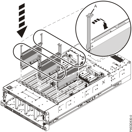
-
Place the SAS cables (A) against the foam of the SAS cable support
(B) as shown in the following figure. With your fingers holding the SAS
cables against the foam, lower the SAS cable support (B) and SAS cables
straight down between the alignment pins (C).
The foam holds the cables against the side of the system and prevents air from blowing through the side channel. Do not simply press the support (B) down in the channel on top of the cables.
Figure 24. Replacing the SAS cable holder 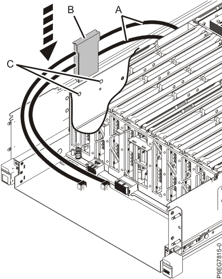
-
Replace the service access cover.
- Lower the cover (A) onto the system unit. Ensure that the cover alignment pins (C) on each side of the cover fit into the matching slots in the chassis.
- Slide the cover (A) onto the system unit.
- Close the release latches (B) by pushing it in the direction that is shown in the following figure.
Figure 25. Installing the service access cover 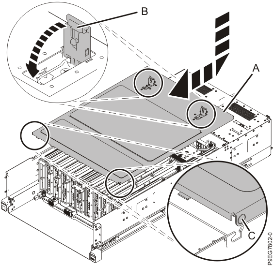
-
Route the SAS cables around to the front of the system.
Figure 26. Routing the SAS cables 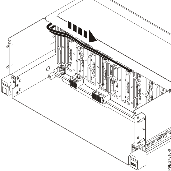
- Remove the system-to-rail locking clips.
- Complete the following steps to place the system
in the operating position.
- Unlock the blue rail safety latches (A) by lifting them upward as shown in the following figure.
- Push the system unit back into the rack as shown in the following figure until both system unit release latches lock into position.
Note: Slide the system unit slowly into the rack to ensure that your fingers do not get caught in the side rails.Figure 27. Placing the system into the operating position 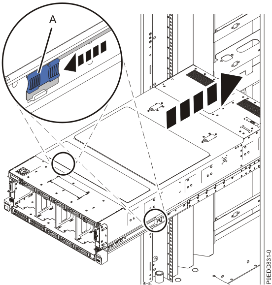
-
To replace the disk drive backplane, complete the following steps:
-
Using two hands, grasp the disk drive backplane where indicated by the blue squares in the
following figure. Partially insert the disk drive backplane straight into the front of the
system.
Do not yet fully insert the disk drive backplane; leave about a 2.5 cm (1 in) gap at the rear of the disk drive backplane.
Figure 28. Partially replacing the disk drive backplane 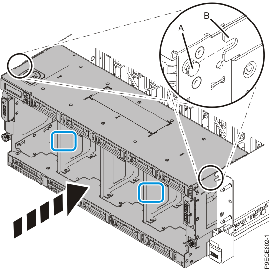
-
Move the system unit (A) to be at most 20.3 cm (8 in) from the rack as
shown in the following figure. Ensure that any cables do not catch or bind as you move the
system.
Figure 29. Partially sliding the system into the rack 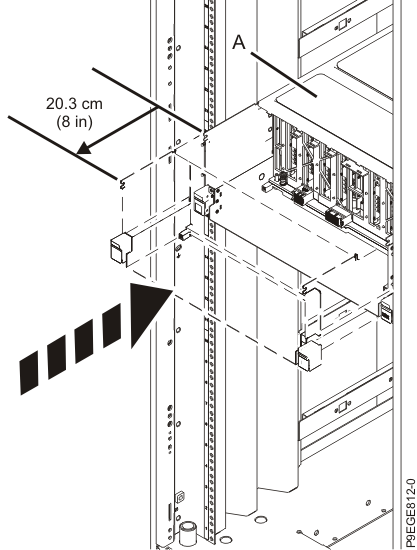
-
Using the connector labels near the ends of the SAS cables, attach
the SAS cables to the rear of the disk drive backplane as shown in the following figure.
Hold the disk drive backplane while you attach the SAS cables to prevent the disk drive backplane from tipping forwards out of the system.
Figure 30. Attaching the SAS cables to the base function disk drive backplane 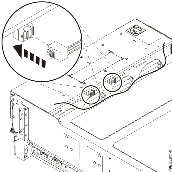
Figure 31. Attaching the SAS cables to the expanded function disk drive backplane 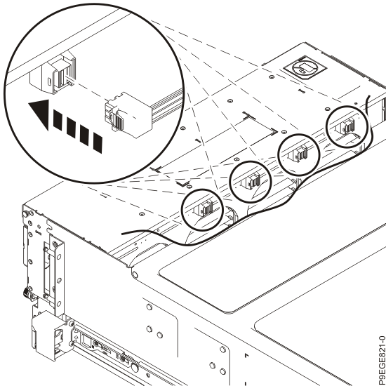
-
Again using two hands, push the disk drive backplane back into place, ensuring that the
alignment pins at (A) insert into the slots at
(B).
Figure 32. Replacing the disk drive backplane 
-
Push the system unit (A) back into the rack until both release latches
of the system unit lock into position. Ensure that any cables do not catch or bind as you push in
the system.
Figure 33. Placing the system into the operating position 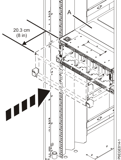
-
Secure the disk drive backplane with two recessed screws at (A). Use a 4
mm ball-end hex driver (130 mm long, IBM part number 02EA546) to tighten the screws.
First, set the screw threads on one side, then the other. Then, evenly tighten the screws on both sides until both sides are seated. If you screw in one side of the disk drive backplane completely, the disk drive backplane might twist, preventing the disk drive backplane from properly seating in the chassis.
- Secure the disk drive backplane with two screws at (B).
Figure 34. Fastening the screws for the disk drive backplane 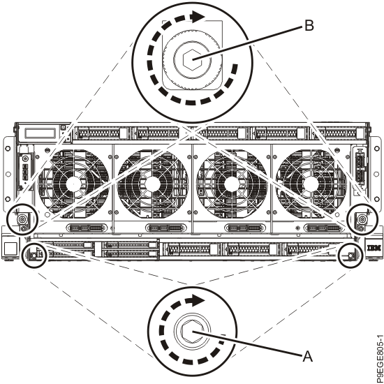
-
Using two hands, grasp the disk drive backplane where indicated by the blue squares in the
following figure. Partially insert the disk drive backplane straight into the front of the
system.
-
Replace all the fans in the disk drive backplane.
- Ensure that the fan handle (A) is open as shown in the following figure.
- Hold on to the fan handle and by using your hand to support the bottom of the fan, push the fan into its slot as shown in the following figure.
- Push the fan handle in the direction that is shown in the following figure.
- Push against the left front of the blue touch point latch (B) with your thumb and then slightly pull the latch at (C) with your index finger. This action opens the latch.
- Continue to push in the lever with your thumb until the latch is fully seated at (C).
Figure 35. Replacing the fans 